Supplementary
Material
Shield Fields: Modeling and Capturing 3D Occluders
Douglas Lanman1,2 Ramesh Raskar1,3 Amit Agrawal1 Gabriel Taubin2
1Mitsubishi Electric Research Laboratories (MERL) 2Brown University 3MIT Media Lab
 |
 |
 |
Abstract
We describe a unified
representation of occluders in light transport and photography using
shield fields: the 4D attenuation function which acts on any light
field incident on an occluder. Our key theoretical result is that
shield fields can be used to decouple the effects of occluders from the
incident illumination. We first describe the properties of shield
fields in the frequency-domain and briefly analyze the “forward”
problem of efficiently computing cast shadows. Afterwards, we apply the
shield field signal-processing framework to make several new
observations regarding the “inverse” problem of reconstructing 3D
occluders from cast shadows – extending previous work on
shape-from-silhouette and visual hull methods. From this analysis we
develop the first single-camera, single-shot approach to capture visual
hulls without requiring moving or programmable illumination. We analyze
several competing camera designs – ultimately leading to the
development of a new large-format, mask-based light field camera that
exploits optimal tiled-broadband codes for light-efficient shield field
capture. We conclude by presenting a detailed experimental analysis of
shield field capture and 3D occluder reconstruction.
Contributions and Limitations
(i) Contributions to the theoretical analysis of volumetric occlusion:
(ii) Contributions to modulation of light fields:
(iii) Contributions to shadowgram-based imaging:
(iv) Future directions to overcome prototype system limitations:
Simulations: Understanding System Limitations and Reconstruction Accuracy
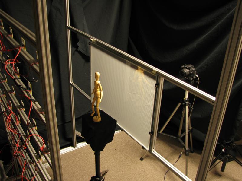
Photographic Demonstration: Basic Hardware
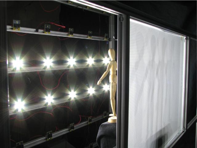
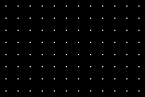
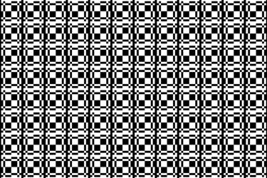
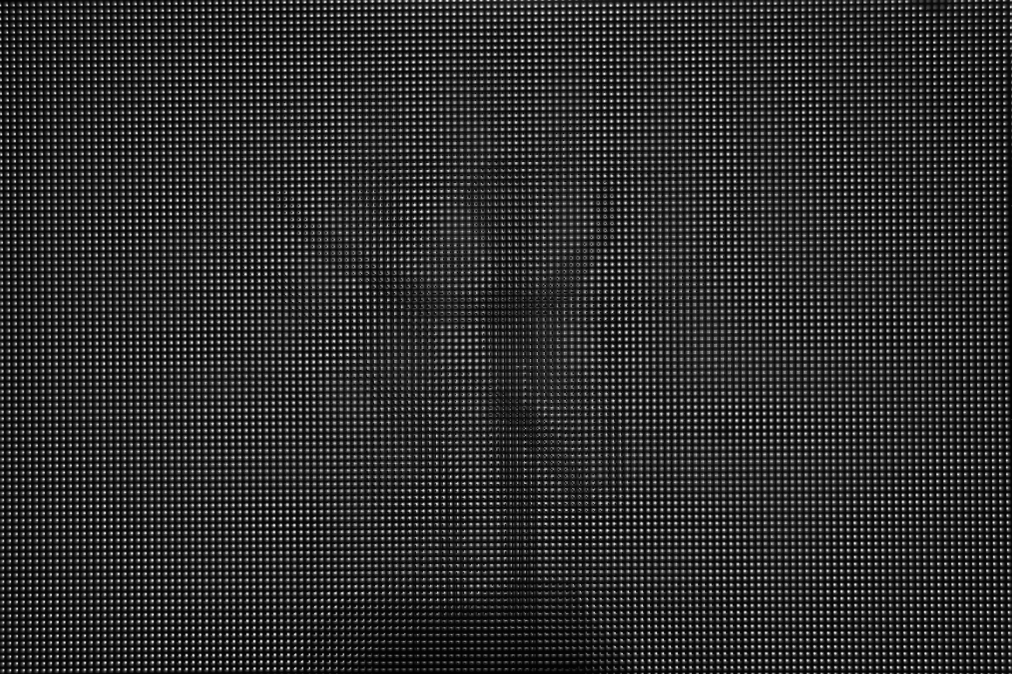
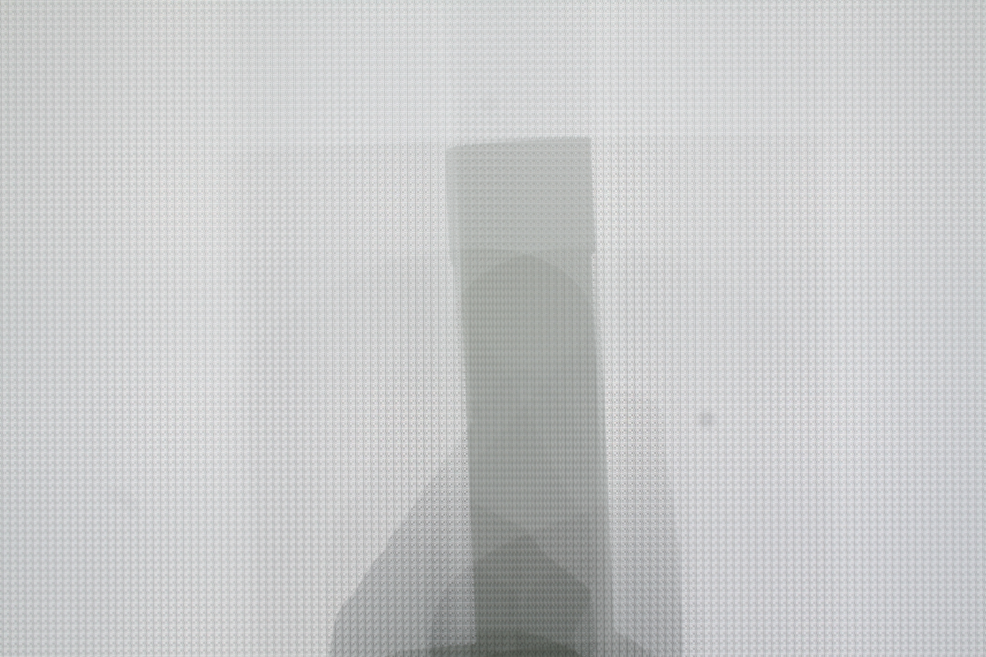
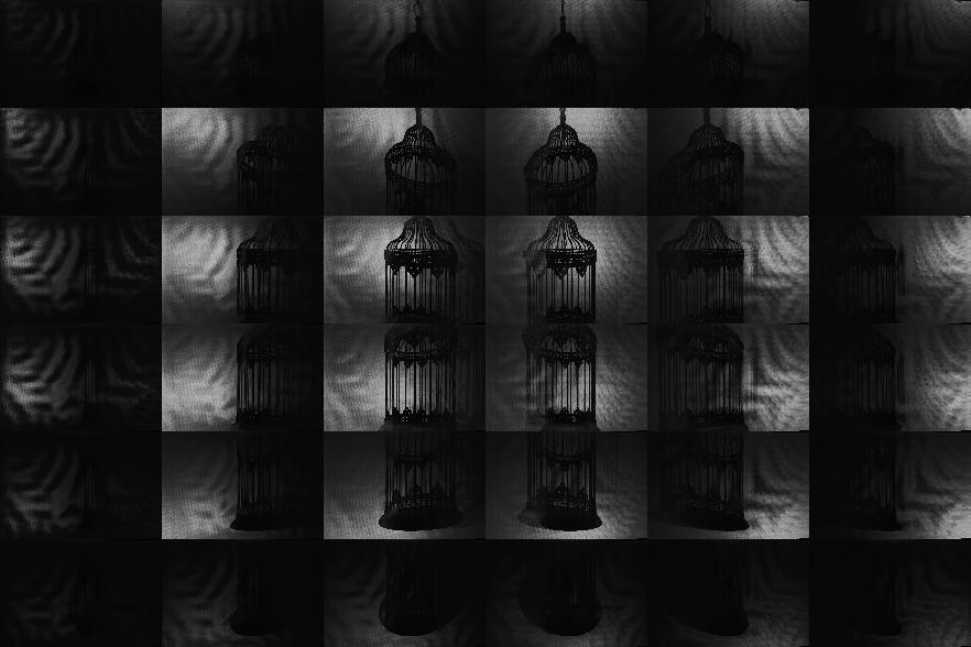
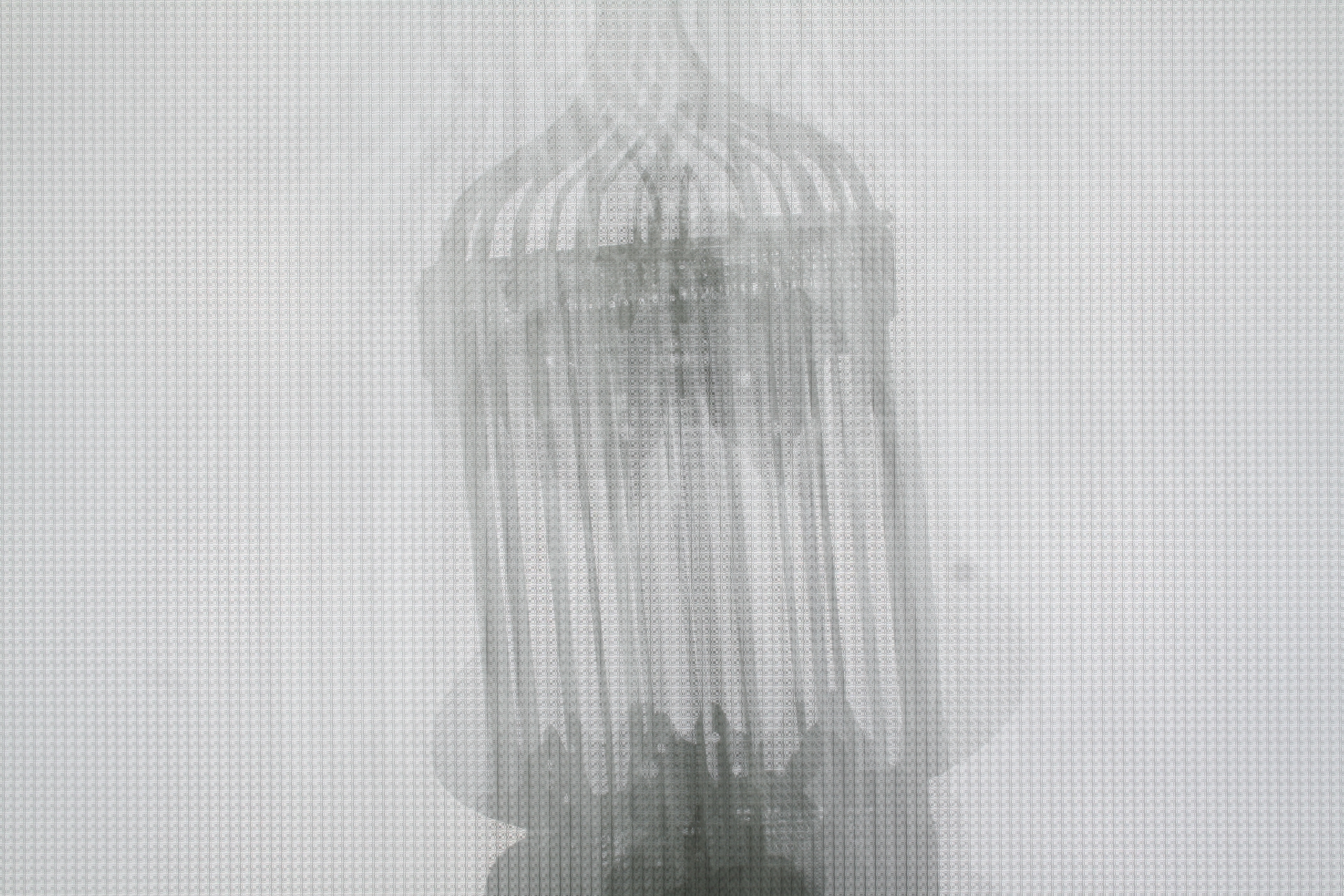
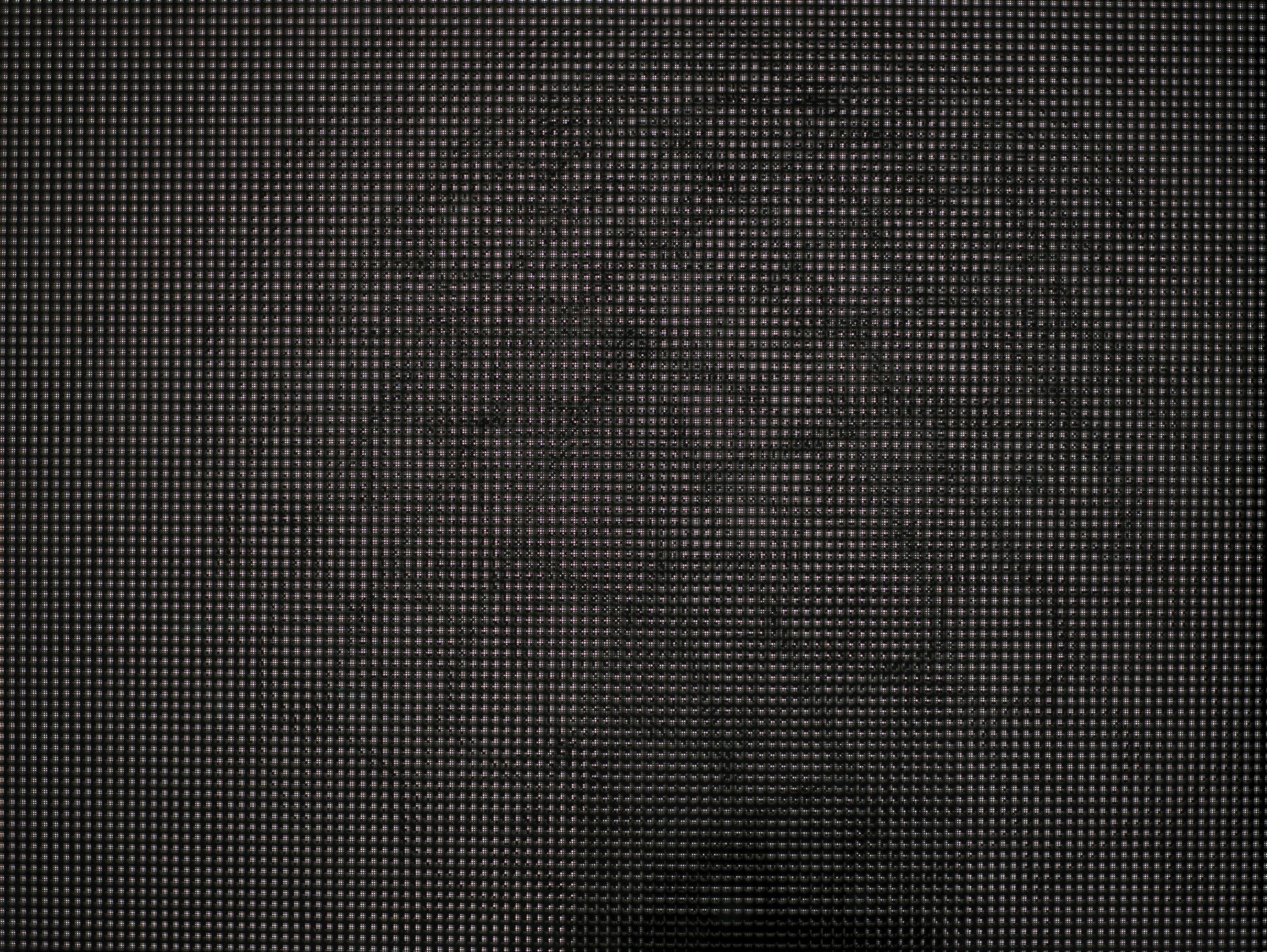
Although our focus is on theoretical discussion, we built a proof-of-concept system to evaluate the practical considerations for such designs, including: mask printing issues, optical alignment, and system calibration. Our photographic (i.e., still-image) prototype is shown below. The imaging system was composed of four primary elements: (1) a single 8.0 megapixel Canon EOS Digital Rebel XT camera, (2) a 75 cm x 55 cm diffusing screen made of Grafix GFX clear vellum paper, (3) three sheets of 3 mm thick laminated safety glass, and (4) a set of interchangeable masks printed at 5,080 DPI on 100 micron polyester base using a Heidelberg Herkules emulsion printer. The diffusing screen was placed between the first two sheets of glass closest to the camera. The various pinhole array and tiled-MURA masks were then placed between the second and third sheets of glass. The diffuser/glass/mask assembly was rigidly mounted to an aluminum frame. The illumination system was composed of three primary elements: (1) a 6x6 array of Philips Luxeon Rebel cool-white LEDs, distributed uniformly over a 1.2 m x 1.2 m region, with each 3 mm wide LED producing 180 lumens at 700 mA, (2) a regulated power supply, and (3) an aluminum scaffold constructed using the 80/20 modular framing system to allow simple adjustments to the LEDs. The illumination plane was separated from the mask by 65 cm. Since our camera records a 3456 x 2304 image, we printed pinhole arrays and tiled-MURA masks with 150x100 pinholes, each providing an 11x11 pixel subview. That is, the camera oversampled both the spatial and angular dimensions by a factor of two. The masks were separated from the diffuser by approximately 2.7 mm in order to recover the shadowgrams produced by each LED. The "photographic" pinhole array and tiled-MURA masks are shown below.
Video-rate Demonstration: Basic Hardware
Our system is also capable of video-rate visual hull reconstruction. In order to demonstrate this capability, we substituted a Point Grey Grasshopper video camera (GRAS-20S4M/C) for the photographic camera used in previous experiments. This camera recorded 1600x1200 8-bit RGB images at 15 fps using a Computar 12.5 mm TV lens (V1312). The illumination system (i.e., the LED array) was identical to that used in the still-image photographic experiments. Due to the reduced resolution of the video camera, the pinhole array and tiled-MURA masks were printed at half the spatial resolution as the photographic masks. As a result, the light field (recovered independently for each frame) is composed of a 6x6 array of approximately 75x50 pixel images (one for each light source). The volume renderings were generated using Drishti. (The transfer function was manually-tuned so that high-confidence regions are shaded red, moderate-confidence regions in green, and low-confidence regions in blue.) The "video-rate" pinhole array and tiled-MURA masks are shown below.
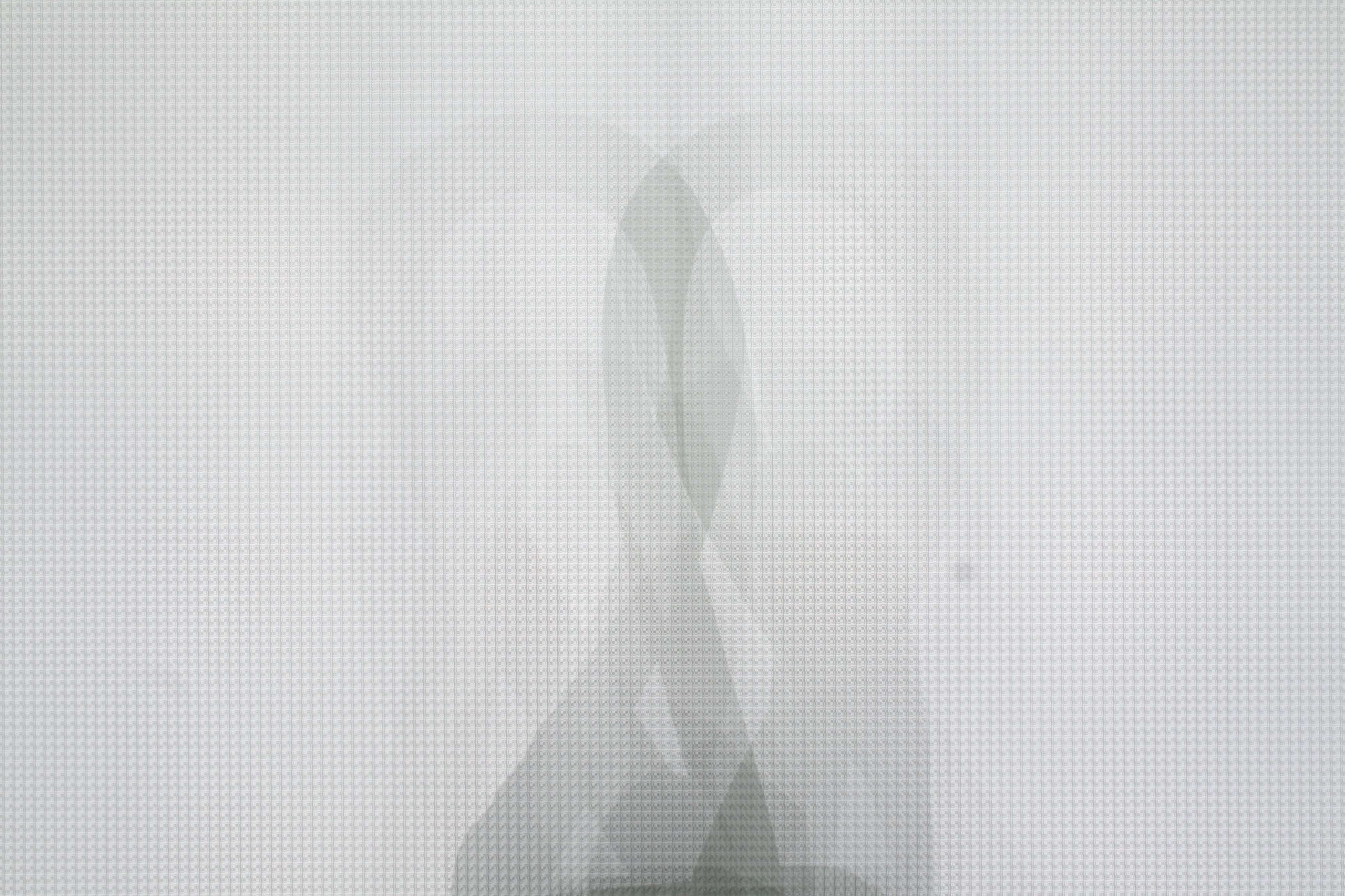
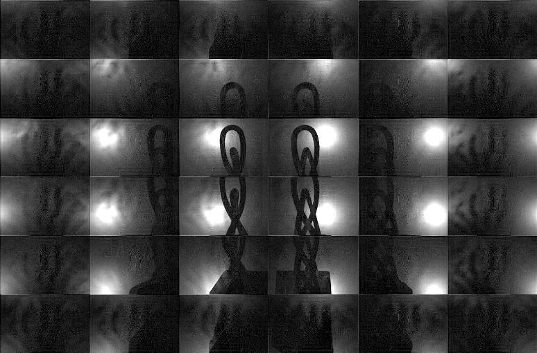
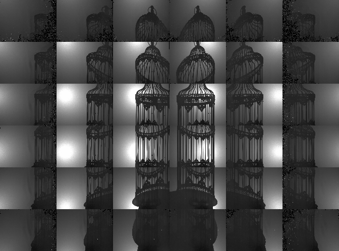
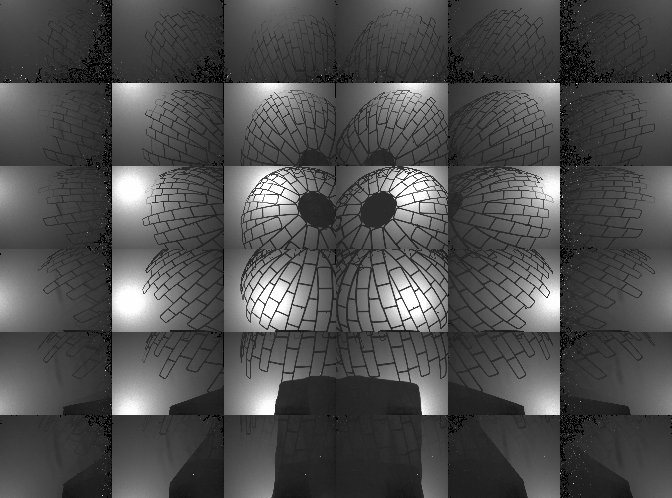
Results: Shadowgram Recovery and Visual Hull Reconstruction using the Photographic and Video-rate Prototypes
Comments on Photographic Results:
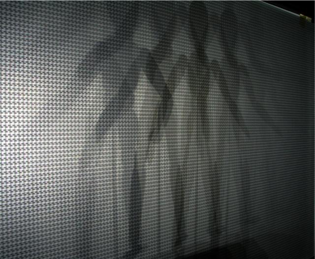
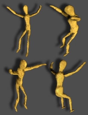
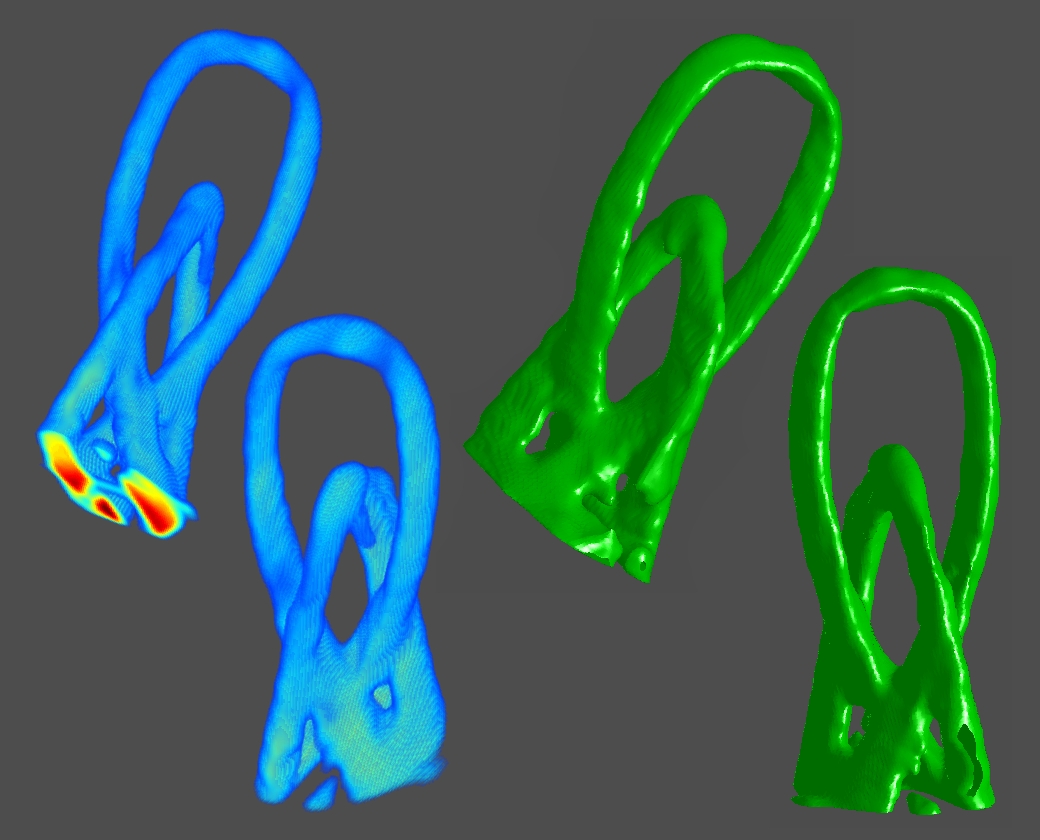
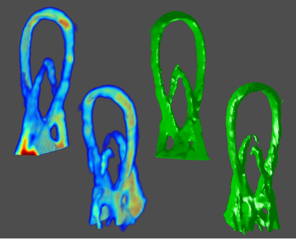
This table summarizes the performance of our prototype implementation for a variety of objects; the first column shows a summary of objects which we have tested with our system. The second through seventh columns compare the performance of the "pinhole array" and "tiled-MURA" masks using our photographic prototype. (Note that the object placement and orientation differs between the "pinhole array" and "tiled-MURA" examples.) We again emphasize that, in our method, each frame is reconstructed independently. These photographic results demonstrate that single-frame reconstruction was achieved. We also note that the benefits of the "tiled-MURA" mask are clear from these examples; in each case, the pinhole array required a 30 sec. exposure, whereas the tiled-MURA mask required only 0.25 sec. (over 100 times shorter). Note that the visual hull reconstructions are displayed as volume renderings and isosurfaces. (The transfer function for the volume renderings was manually-tuned so that high-confidence regions are shaded red, moderate-confidence regions in green, and low-confidence regions in blue.) While qualitatively similar, we note that obtaining individual shadowgrams using "tiled-MURA" masks requires better calibration in order to obtain the proper phase-shifts for demodulation (unlike the "pinhole array" images). Please note that all videos were encoded using the Xvid codec.
Comments on Video-rate Results:
The resolution of current video camera technology limits the degree to which we could demonstrate real-time capture; we have, however, implemented a preliminary video-rate version of our prototype using a Point Grey Grasshopper video camera capable of recording 1600x1200 8-bit RGB images at 15 fps; typical results are demonstrated in columns eight through thirteen. Note that, since these dynamic examples are a proof-of-concept to confirm video-rate performance, only a single example is considered: that of a rigidly-mounted mannequin translated throughout the reconstruction volume over 10 seconds. Note that the volume renderings were also generated using Drishti. (The transfer function was again manually-tuned so that high-confidence regions are shaded red, moderate-confidence regions in green, and low-confidence regions in blue.) Please click on any image to view at higher-resolution or to view the associated video for dynamic examples. Due to the reduced resolution of the video camera, the recovered light field consists of a 6x6 array of approximately 75x50 pixel images for the dynamic examples, whereas the photographic implementation allowed the recovered of a 6x6 array of approximately 150x100 pixel images. Again, the most significant practical limitation of our system is the diffuser (and the video-rate results show similar limitations in this regard). We believe that these limitations can be overcome with careful engineering and utilization of improved optical components. In the future, higher resolution projectors will lead to similar improvements in commercial rear-projection diffusers. Alternatively, as discussed in Section 8, we could increase the size of the system; since the diffuser PSF stays constant, but the size of a camera pixel increases, the effective angular resolution will increase. Finally, we emphasize that our system will scale with improvements in camera sensors. For example, with a 100 megapixel camera, our design will capture a 10x10 array of 1 megapixel images; in comparison, consider the challenge and costs of building a comparable system with 100 individual cameras.
General Comments on Current Limitations:
We again emphasize that, while the current results show some reconstruction errors, we believe careful engineering, the inclusion of future diffuser technology, and high-resolution consumer cameras will greatly improve the quality of the results and the practicality of the proposed architecture. When viewing these results, please weigh current limitations against the considerable promising new directions enabled by our theory and system, including: (1) allowing single-camera techniques to compete, for the first time, with complex multi-camera systems in the arena of motion capture, and (2) developing high-throughput attenuation masks for use in heterodyne light field cameras and large-format photography.
Light Source Calibration Procedure
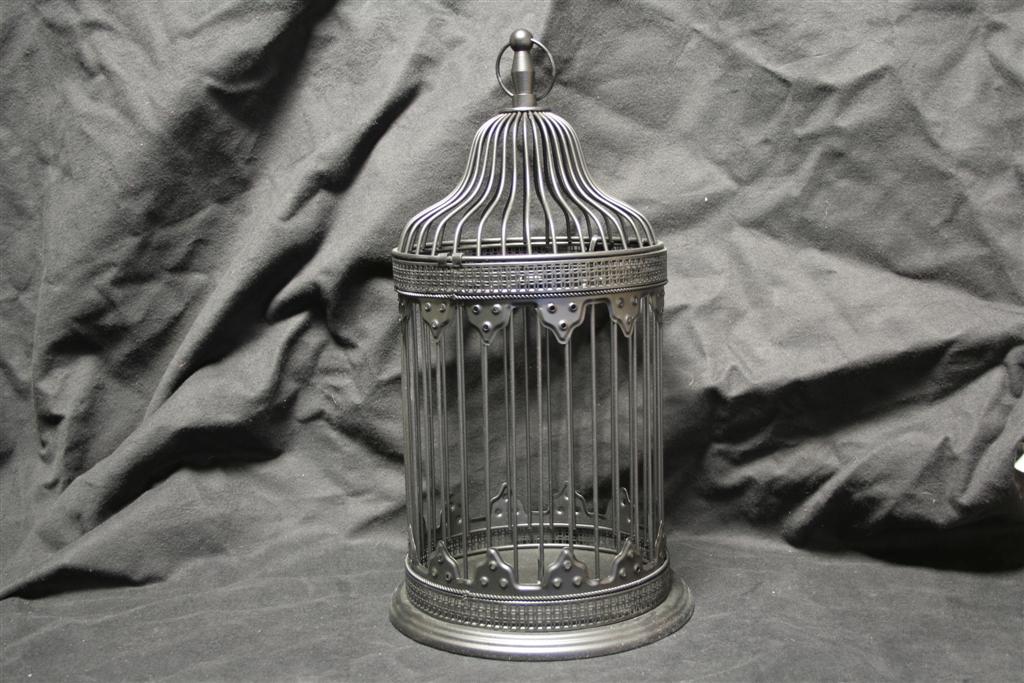
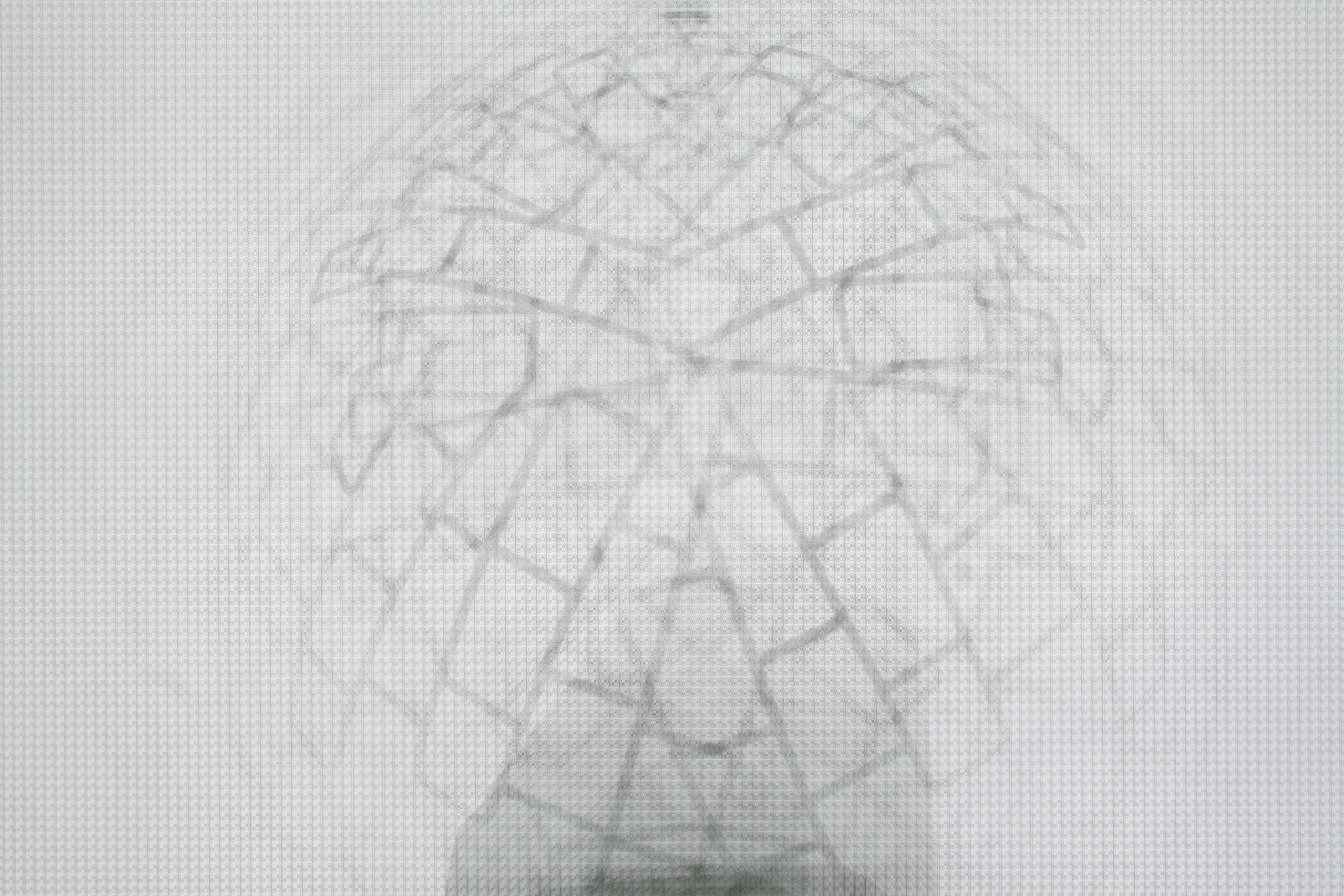
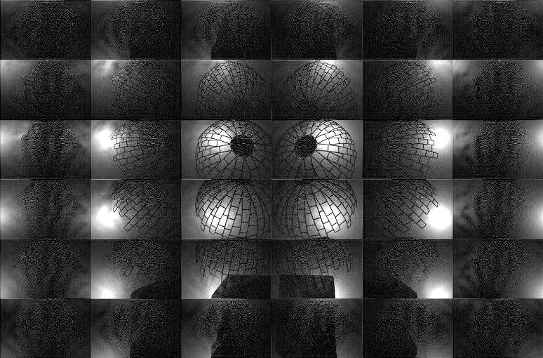
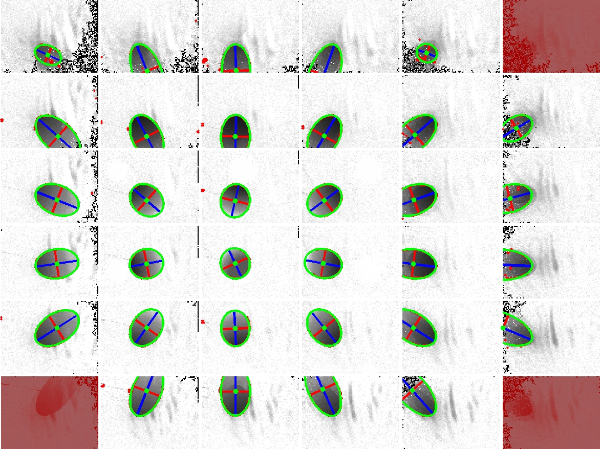
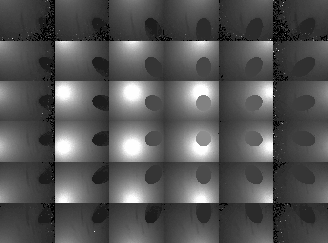
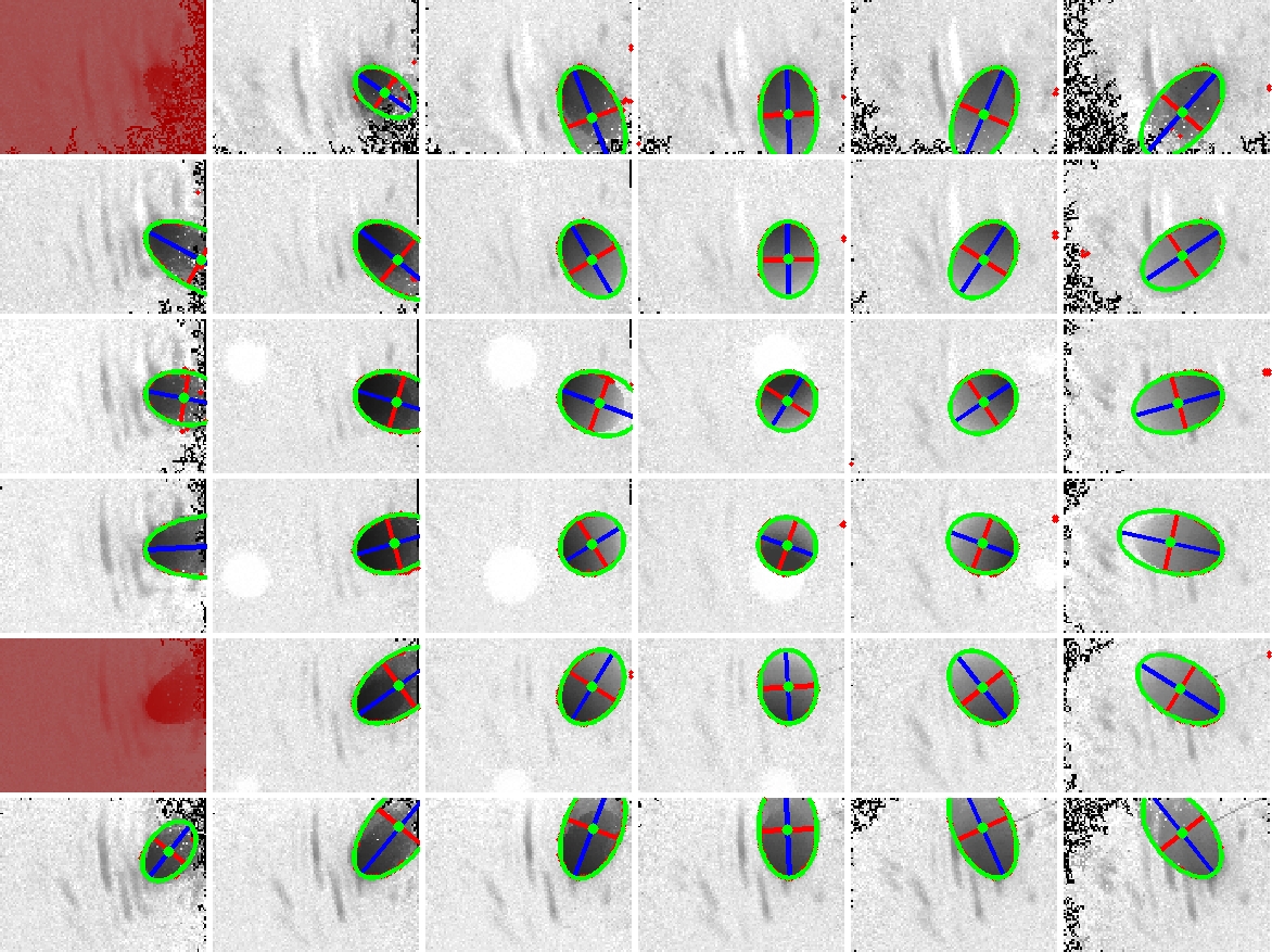
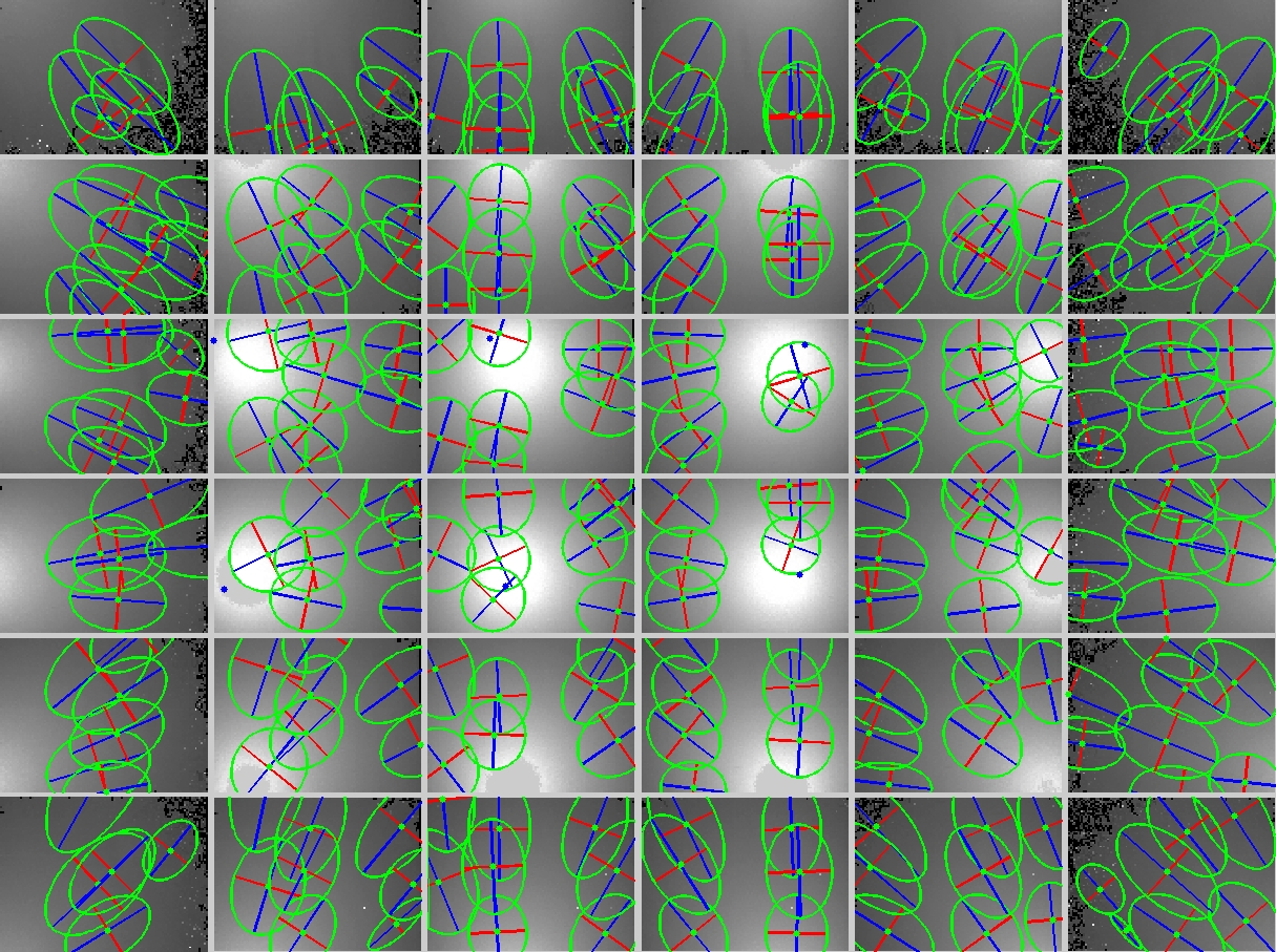
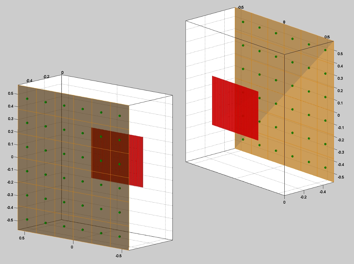
In order to recover the visual hull from the individual shadowgrams, we require precise estimates of the 3D location of each point source. Previously, Yamazaki et al. [2007] and Savarese et al. [2001] studied the problem of estimating the position of point light sources. For our system, we adopted a method similar to Yamazaki et al. [2007]. As discussed in that work, the position of a point light can be recovered by observing the shadows due to spheres placed within the scene. In fact, they show that one can solve for the position of a light in 3D given two or more images of a single sphere with an unknown radius. In this work, we used a single sphere, with a 12.7cm diameter, and recorded a set of shadowgrams as the sphere was translated through the reconstruction volume. Typical shadowgrams are shown below. Afterwards, we used a least-squares ellipse-fitting routine to estimate the shadow boundary. To minimize the effects of outliers and shadowgram artifacts, we further applied RANSAC within the ellipse-fitting procedure. Typical fitting results are shown below (with the ellipse boundary shown in green and the major/minor axes shown in blue/red). The complete set of ellipses are also shown below, where we observe that, in 2D, their major axes intersect the closest point in the diffuser to each light source. Again, one must apply RANSAC to minimize the effects of poorly-fit shadow boundaries. Finally, the full ellipse parameters are used to recover the depth of each light source. The recovered light source positions are shown below. In this example, we have found the best location of the light source array, given the constraint that the lights are uniformly-distributed and that the predicated shadow boundaries are as close as possible to the detected ellipses.
Compensating for Refraction within the Multiple Glass Panes
Observations of Per-Pinhole Barrel Distortion due to Glass Refraction:
In the prior results, we ignored the effect of refraction due to the multiple thin glass panes. In general, we find that refraction is a significant issue and, to obtain the highest-quality shadowgrams, one must compensate for its effects. The effects of refraction are readily observed by illuminating the scene with the 6x6 LED array and recording a shield field photograph using a pinhole array mask. As shown in the images above and in the inset region below, a per-pinhole barrel distortion is clearly present. If refraction was not an issue, then the image of each point light source would be located in a uniformly-spaced grid (rather than a barrel-distorted pattern). In our prototype, neither the attenuating masks nor the diffuser are rigid. As a result, we must use a minimum of three sheets of approximately 2.7 mm glass to separate the mask from the diffuser and hold both in fixed positions.
Theoretical Explanation for Barrel Distortion:
Generally, the thickness of the glass after the diffuser does not significantly impact the barrel distortion, however it does slightly increase the effective PSF of the imaging system. Surprisingly, the thickness of the first sheet of glass (between the mask and the light sources) is important and should be as thick as possible. This is somewhat counterintuitive, however it is easily explained using geometric optics. First, notice that the second sheet of glass (between the mask and diffuser) must have the precise thickness required for heterodyne detection (i.e., the mask-diffuser separation is given by the desired spatial/angular resolution and the geometric placement of the lights relative to the diffuser). Since the refractive index of crown glass is around 1.5, the effect of the center glass sheet will be to bend each incident ray towards the surface normal of the pane – directly causing the observed barrel distortion. As a thought experiment, now consider varying the thickness of the first sheet of glass from zero (i.e., no glass) to the distance to the light array (i.e., infinite). If the glass thickness is zero, then we have the case of a single glass sheet between the mask and diffuser, and significant barrel distortion occurs. If we enclose the lights within the glass, then no refraction occurs before the pinhole or before the diffuser and it is as if the system is in air. As a result, increasing the thickness of the first glass sheet slightly reduces barrel distortion. In practice, however, barrel distortion cannot be eliminated in our current design. In the future, we propose using rigid masks and diffusers to avoid refraction. Most importantly, we observe that if a revised design only eliminated the central glass pane, then barrel distortion would be completely eliminated for the pinhole array – even if the other two panes of glass remained in the system.
Compensating for Barrel Distortion in Pinhole Arrays:
While the prior results demonstrate successful shadowgram recovery, we notice that, by ignoring refraction, the demodulated pinhole array and tiled-MURA results exhibit various moiré-type patterns. This is a result of assuming that the images of the point sources are located on a uniform grid. Because the barrel distortion is minor, this does not prevent either pinhole or heterodyne masks from functioning, however better results can be achieved by compensating for refraction. Currently, this procedure can only be applied to pinhole array images, but we expect future work to examine similar solutions for heterodyne demodulation. To compensate for refraction, we simply photograph an empty scene using a pinhole array mask and a single light source at a time. In our prototype, we collect 36 images – one for each LED. Afterwards, we detect the subpixel peaks (using intensity centroids) for each pinhole image. Finally, after grouping and ordering these peaks, we obtain the per-pinhole barrel distortion (as shown below on the right). Afterwards, we use the subpixel peaks to interpolate any given shield field photograph. As shown in the following section, this procedure produces enhanced shadowgrams with minimal crosstalk and with better performance for large angles of incidence to the diffuser.
Results: Refraction-Compensated Shadowgram Recovery and Visual Hull Reconstruction
We repeated the previous photographic shield field experiments using the refraction compensation procedure. In addition, because the per-pinhole barrel distortion may cause image peaks to move closer together, we also used a higher-resolution camera to prevent undersamping. In these examples we used a 22 megapixel Mamiya 645ZD camera with an 80mm f/2.8 AF lens. In addition, we photographed the diffuser using the maximum setting of f/2.8 – significantly reducing the necessary exposure time for the pinhole array when compared to the Canon EOS Digital Rebel XT. Typical results are shown below. Note that the peripheral shadowgrams (corresponding to large angles of incidence to the diffuser) are more robustly recovered than before, where the remaining "salt-and-pepper" noise results from peak-localization errors in low-SNR regions of the recovered shadowgrams. Similarly, visual hull reconstructions using the refraction-compensated shadowgrams recovered finer object details.
Conclusion
Occluders are becoming valuable for a range of Computational Photography research problems. We have described a unified representation of occluders in light transport and photography using shield fields: the 4D attenuation function which acts on any light field incident on an occluder. We have provided a complete analysis of their application to the inverse problem of occluder reconstruction, leading to the development of new tiled-broadband codes. Our tiled-coding leads to a simple scanning system. We believe we have presented the first single-camera, single-shot approach to capture visual hulls without moving or programmable illumination. Shield fields can be used for several interesting applications in the future, including efficient shadow computations, volumetric/holographic masks, and for modeling general ray-attenuation effects as 4D light field transformations. By creating the signal processing framework and practical light-efficient solutions, we hope to inspire research in novel capture devices based on large area emitters and sensors.
This paper presents the first
alternative that substitutes a single
high-resolution sensor for a wide-area multi-camera array, albeit for a
specific application. In addition, this paper also presents the first
application of frequency-domain analysis to the "inverse" problem
of 3D occluder reconstruction. We present the theoretical notion of
shield fields and show how it leads to: (1) a deeper understanding of
light field modulation, (2) the development of frequency-domain impulse
trains using tiled-broadband codes, and (3) a novel visual hull system
that is the first to allow dynamic scene capture using shadowgrams.
(i) Contributions to the theoretical analysis of volumetric occlusion:
We
develop the notion of shield fields (which can be viewed as a
specialized form of the general 8D reflectance field).
While previous papers, such as Chai [2000] and Durand [2005], have
presented frequency-domain analyses for the "forward" rendering
problem, our paper is the first to focus on the "inverse" problem
of 3D occluder reconstruction.
(ii) Contributions to modulation of light fields:
We
also significantly extend the prior work on heterodyne light field
cameras by Veeraraghavan et al. [2007]; we show that their ad-hoc
"Sum-of-Sinusoids" pattern is surprisingly inefficient for even
marginal increases in angular resolution. We present a new coding
strategy that favorably scales with increasing angular
resolution, transmitting almost three times as much light as theirs
(and over one
hundred times as much light as a pinhole array). In fact, we prove that
the "Sum-of-Sinusoids" pattern is simply one instance of the
tiled-broadband family – an exhaustive set that contains all
possible
heterodyne patterns. These contributions will allow future designers to
find application-optimized masks; for example, in our system we were
able to replace continuous-valued masks with binary masks, allowing a
lower-cost, larger-format, and higher-accuracy printing process to be
employed.
(iii) Contributions to shadowgram-based imaging:
While our proof-of-concept shadowgram capture
system is inspired by those of Yamazaki et al. [2007] and Savarese et
al. [2001], none
of these prior systems were capable of single-shot dynamic scene
capture – even at low resolution. In fact, before our system,
the only
proposed solutions for shadowgram-based reconstruction of dynamic
scenes involved using temporal or wavelength-domain multiplexing.
(iv) Future directions to overcome prototype system limitations:
The most
significant
practical limitation of our system is the diffuser, as
evidenced
by the numerous experimental results documented on this page. We
propose several solutions to overcome limitations in the
current
diffuser. First, we could use a
diffuser with a narrower point spread function. In the future, higher
resolution projectors will lead to similar improvements in commercial
rear-projection diffusers; for example, we have already identified a
550
DPI (46 micron) lenticular-based rear-projection screen
available
from DNP. (Note that this website only contains an early press release
for the diffuser we are describing; technical details are available on
request from DNP
Electronics America.)
Alternatively, as discussed in Section 8, we could increase the size of
the system; since the diffuser PSF stays constant, but the size of a
camera pixel increases, the effective angular resolution will increase.
Finally, we emphasize that our system will scale with improvements in
camera sensors. For example, with a 100 megapixel camera, our design
will capture a 10x10 array of 1 megapixel images; in comparison,
consider the challenge and costs of building a comparable system with
100
individual cameras.
Simulations: Understanding System Limitations and Reconstruction Accuracy
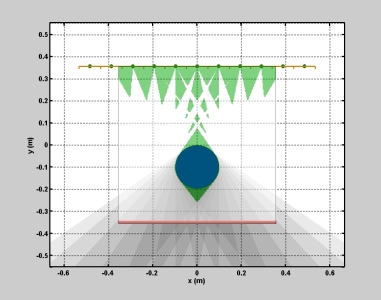
We
implemented a two dimensional simulation of the proposed photographic
demonstration in order to understand system limitations. As shown in
the animation below, the cross section of a 20 cm diameter sphere
(displayed in blue) is shown as it translates through the
reconstruction
volume. (The sphere expands up to a 30 cm diameter at the
beginning of the sequence.) The mask and diffuser are shown at the
bottom in red, whereas the linear point source array is shown
in
yellow (where each green circle denotes a single point source). The
planar
visual hull reconstruction is shown in light green. The simulation was
used to understand the general behavior of reconstruction artifacts
(i.e., "phantom" geometry, reliable reconstruction regions, and minimum
object dimensions). As shown on the right and derived in the paper,
this simulation also confirms our model of predicted spatial resolution
as a function of planar occluder depth. (Please click the simulation
image on the left to view the associated video.)
In addition, as described in Section 6, our simulation was used to assess the impact of heterodyne demodulation on the recovered light field. For our prototype system, we considered adding 5% Gaussian noise to the captured image. On average, we find that heterodyne masks, including SoS and tiled-MURA patterns, decrease the received signal-to-noise ratio (SNR) by about 0.5 dB. The experimental results presented below confirm this observation, with light fields captured using tiled-MURA patterns generally exhibiting increased noise when compared to pinhole arrays. Additional sources of noise and reconstruction errors, as discussed below, arise from refraction within the multiple glass panes.
In addition, as described in Section 6, our simulation was used to assess the impact of heterodyne demodulation on the recovered light field. For our prototype system, we considered adding 5% Gaussian noise to the captured image. On average, we find that heterodyne masks, including SoS and tiled-MURA patterns, decrease the received signal-to-noise ratio (SNR) by about 0.5 dB. The experimental results presented below confirm this observation, with light fields captured using tiled-MURA patterns generally exhibiting increased noise when compared to pinhole arrays. Additional sources of noise and reconstruction errors, as discussed below, arise from refraction within the multiple glass panes.
 |
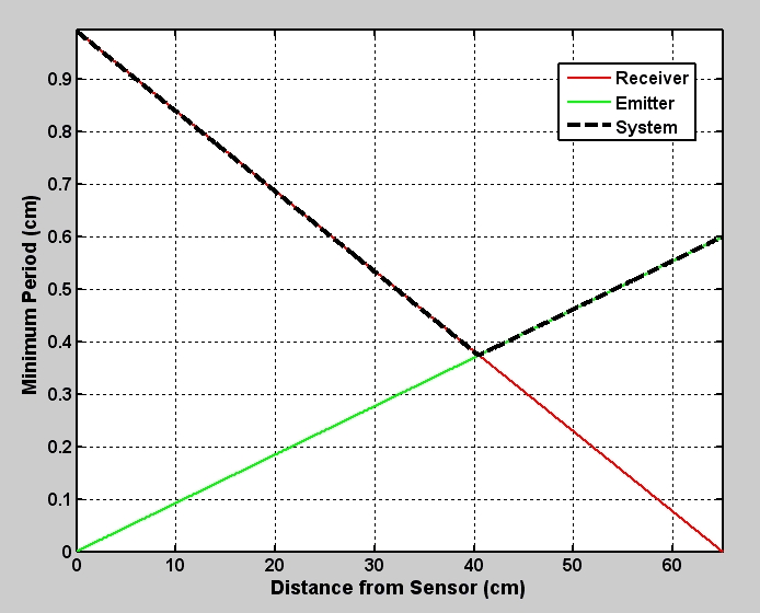 |
| Simulation of Translating Sphere (Cross Section in 2D) | Predicted Spatial Resolution (as a Function of Planar Occluder Depth) |
Photographic Demonstration: Basic Hardware
Although our focus is on theoretical discussion, we built a proof-of-concept system to evaluate the practical considerations for such designs, including: mask printing issues, optical alignment, and system calibration. Our photographic (i.e., still-image) prototype is shown below. The imaging system was composed of four primary elements: (1) a single 8.0 megapixel Canon EOS Digital Rebel XT camera, (2) a 75 cm x 55 cm diffusing screen made of Grafix GFX clear vellum paper, (3) three sheets of 3 mm thick laminated safety glass, and (4) a set of interchangeable masks printed at 5,080 DPI on 100 micron polyester base using a Heidelberg Herkules emulsion printer. The diffusing screen was placed between the first two sheets of glass closest to the camera. The various pinhole array and tiled-MURA masks were then placed between the second and third sheets of glass. The diffuser/glass/mask assembly was rigidly mounted to an aluminum frame. The illumination system was composed of three primary elements: (1) a 6x6 array of Philips Luxeon Rebel cool-white LEDs, distributed uniformly over a 1.2 m x 1.2 m region, with each 3 mm wide LED producing 180 lumens at 700 mA, (2) a regulated power supply, and (3) an aluminum scaffold constructed using the 80/20 modular framing system to allow simple adjustments to the LEDs. The illumination plane was separated from the mask by 65 cm. Since our camera records a 3456 x 2304 image, we printed pinhole arrays and tiled-MURA masks with 150x100 pinholes, each providing an 11x11 pixel subview. That is, the camera oversampled both the spatial and angular dimensions by a factor of two. The masks were separated from the diffuser by approximately 2.7 mm in order to recover the shadowgrams produced by each LED. The "photographic" pinhole array and tiled-MURA masks are shown below.
Video-rate Demonstration: Basic Hardware
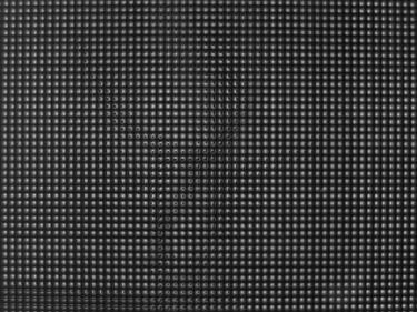
Our system is also capable of video-rate visual hull reconstruction. In order to demonstrate this capability, we substituted a Point Grey Grasshopper video camera (GRAS-20S4M/C) for the photographic camera used in previous experiments. This camera recorded 1600x1200 8-bit RGB images at 15 fps using a Computar 12.5 mm TV lens (V1312). The illumination system (i.e., the LED array) was identical to that used in the still-image photographic experiments. Due to the reduced resolution of the video camera, the pinhole array and tiled-MURA masks were printed at half the spatial resolution as the photographic masks. As a result, the light field (recovered independently for each frame) is composed of a 6x6 array of approximately 75x50 pixel images (one for each light source). The volume renderings were generated using Drishti. (The transfer function was manually-tuned so that high-confidence regions are shaded red, moderate-confidence regions in green, and low-confidence regions in blue.) The "video-rate" pinhole array and tiled-MURA masks are shown below.
 |
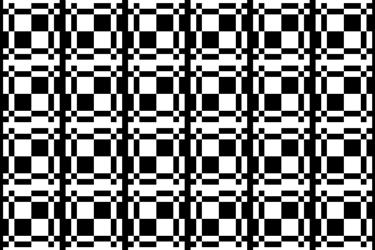 |
| 75x50 pinhole array (pinhole diameter of 409 microns) | 75x50 tiled-MURA pattern (pixel size of 855 microns) |
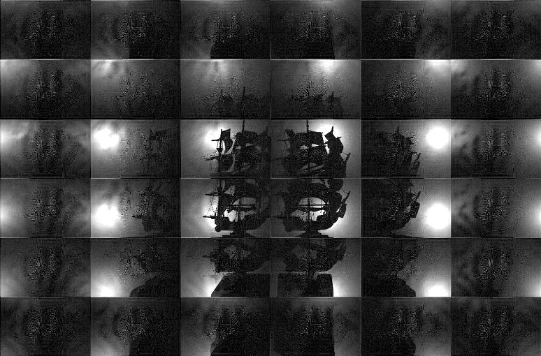
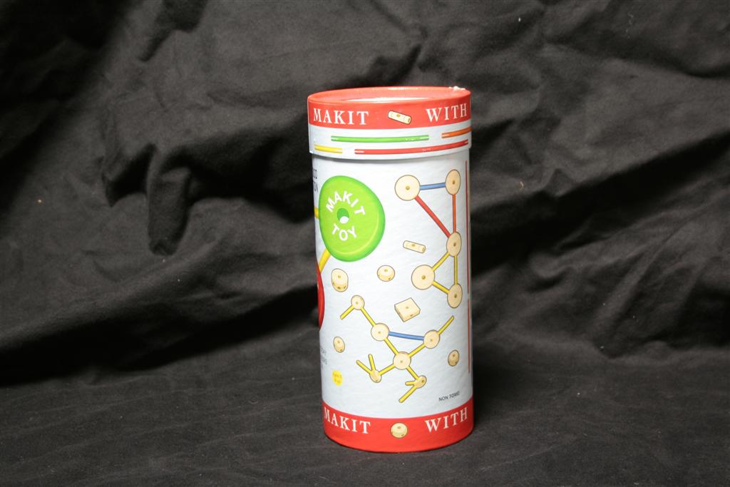
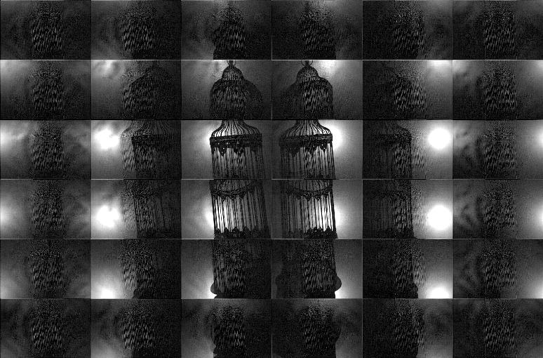
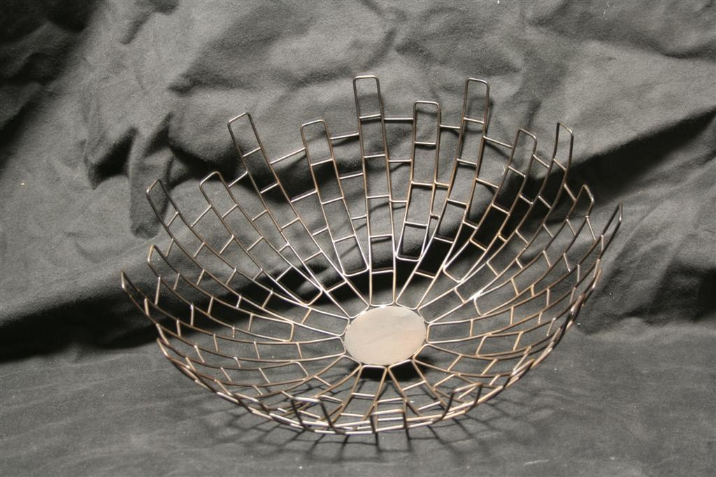
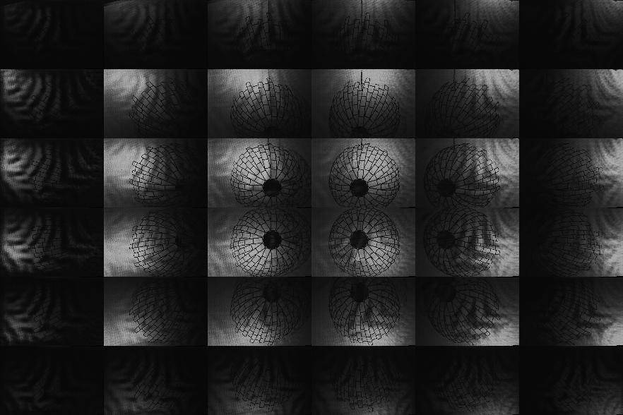
Results: Shadowgram Recovery and Visual Hull Reconstruction using the Photographic and Video-rate Prototypes
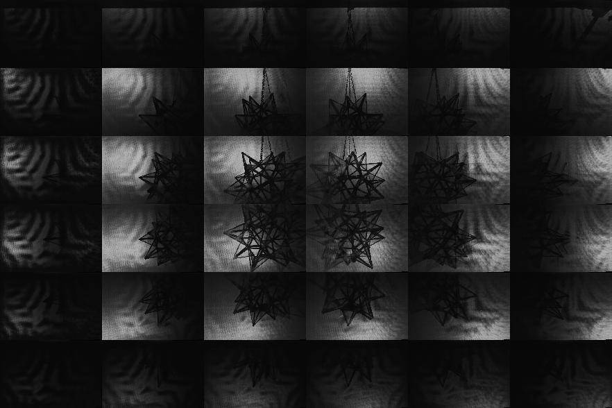
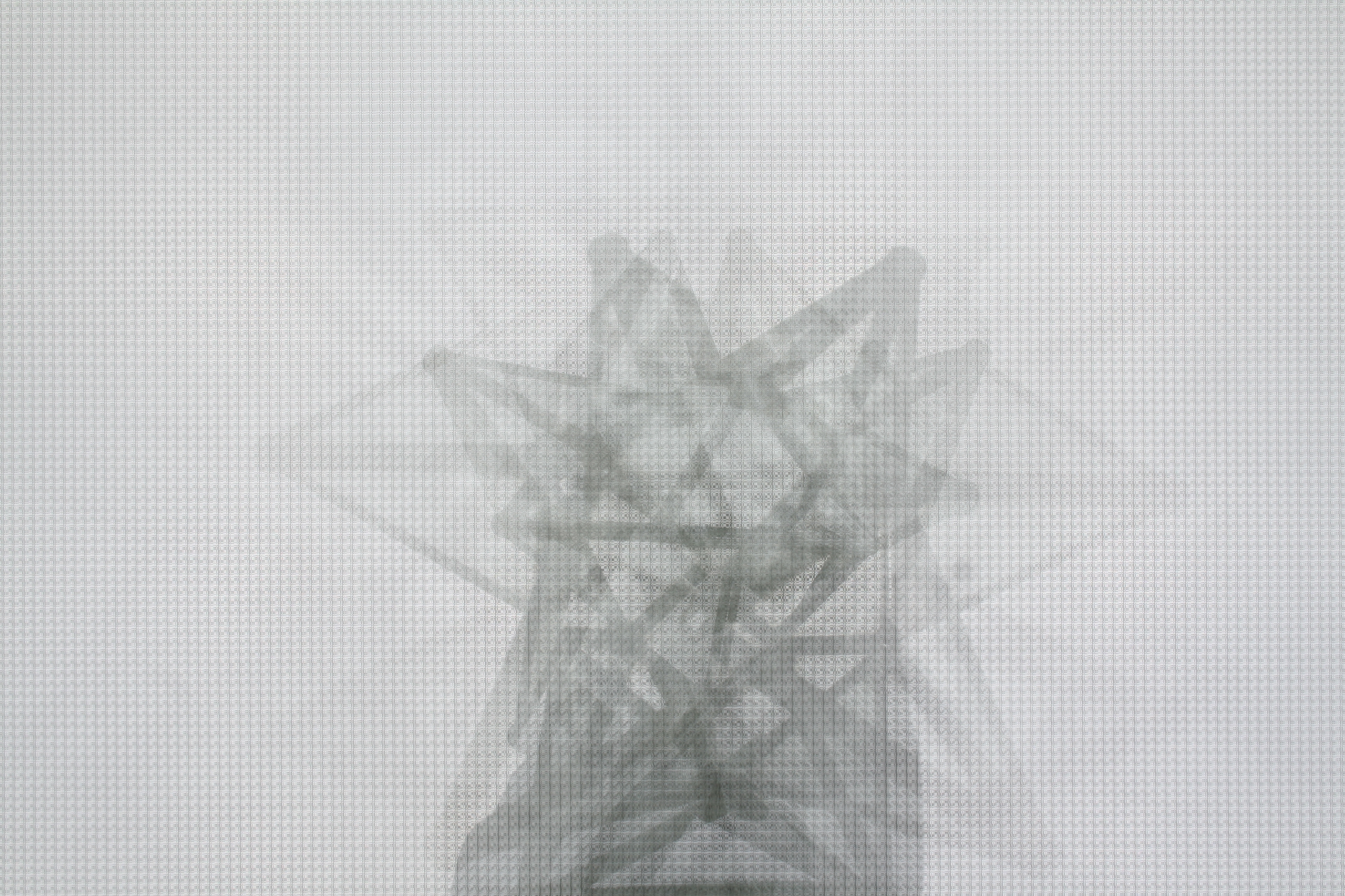
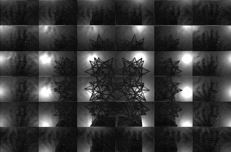
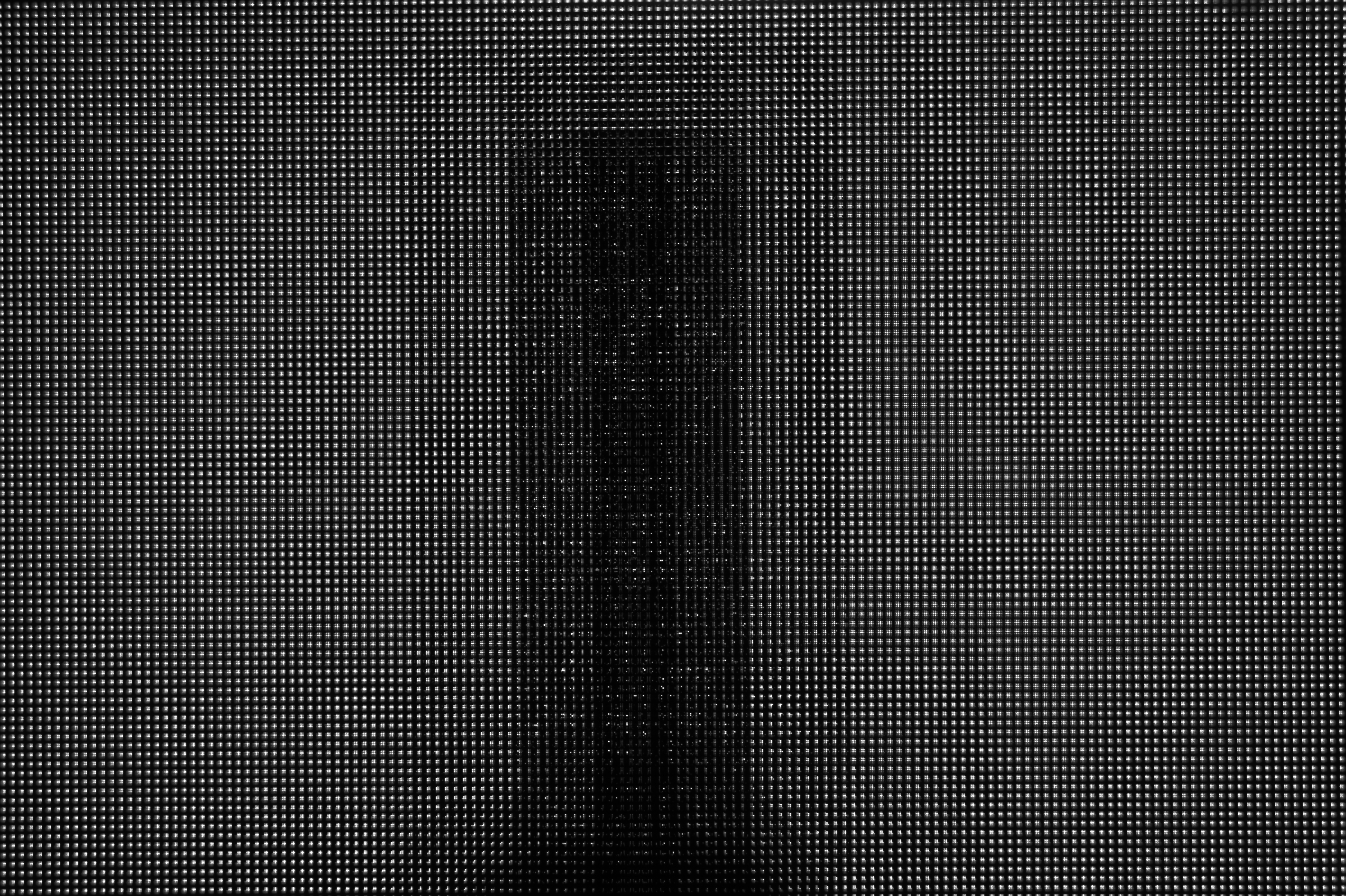
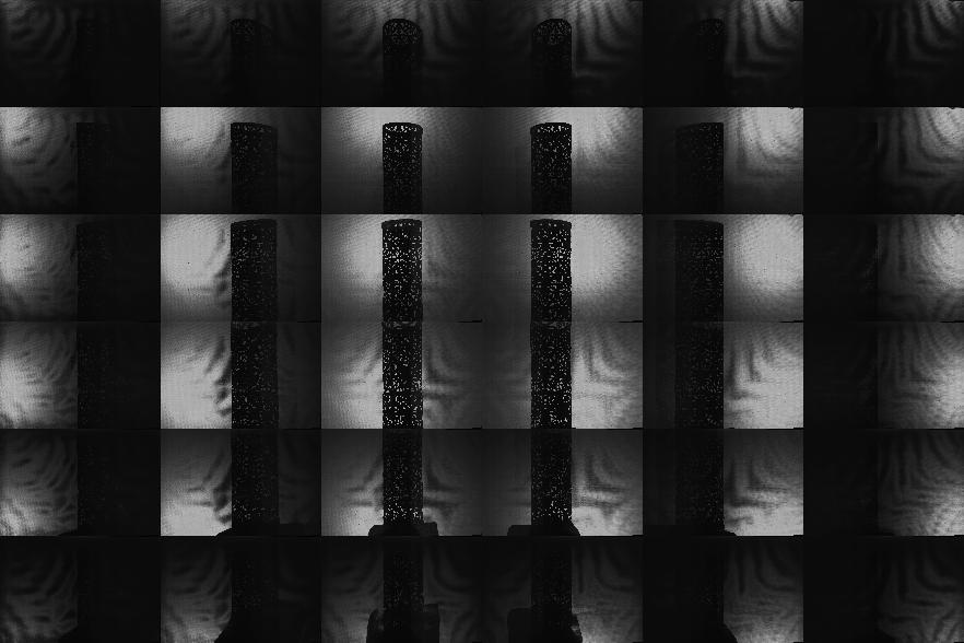
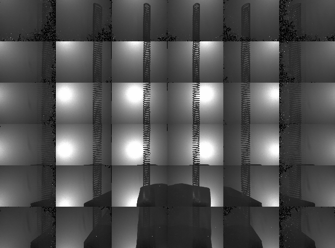
Comments on Photographic Results:
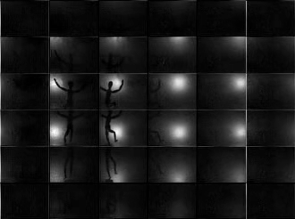
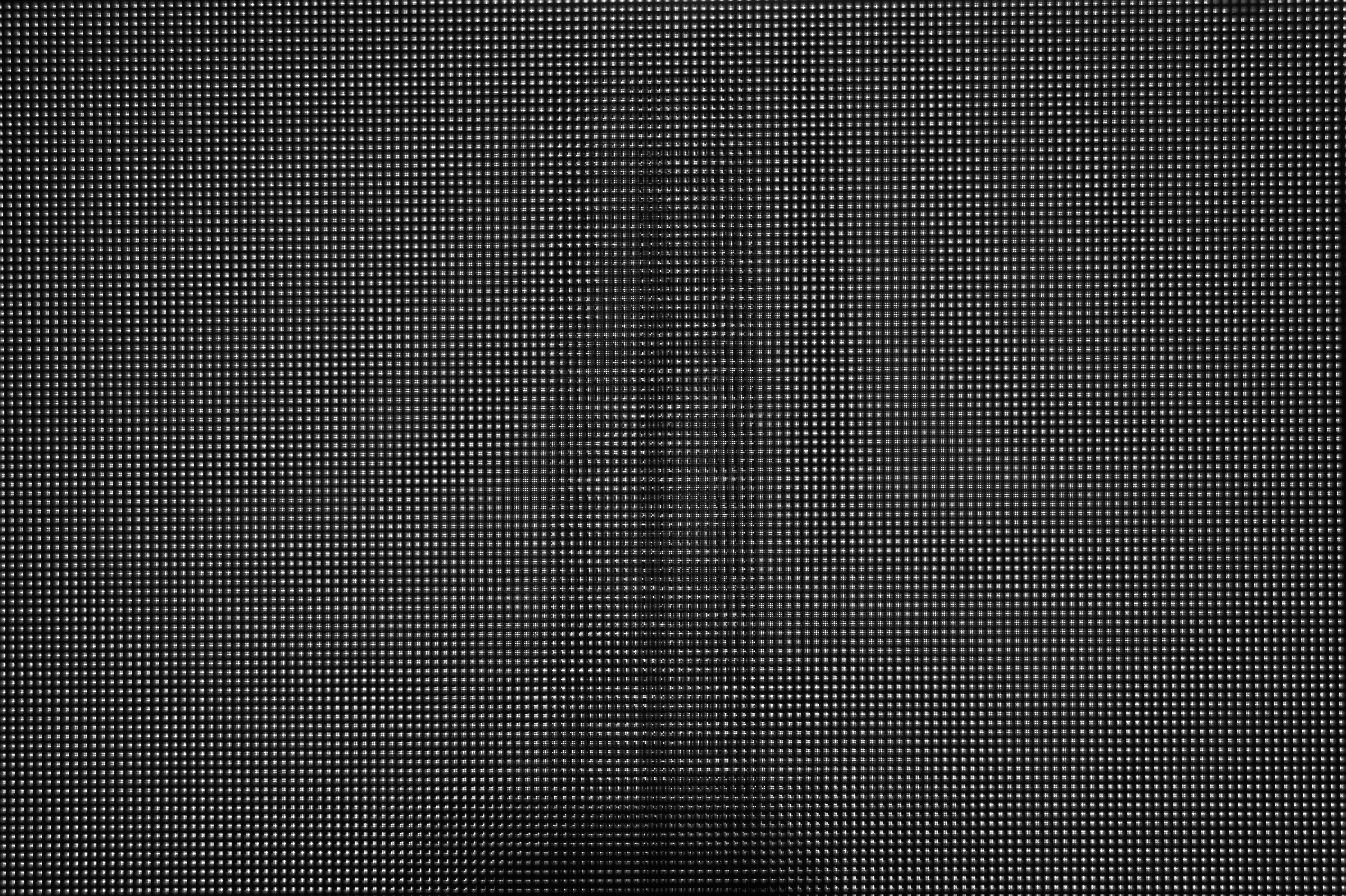
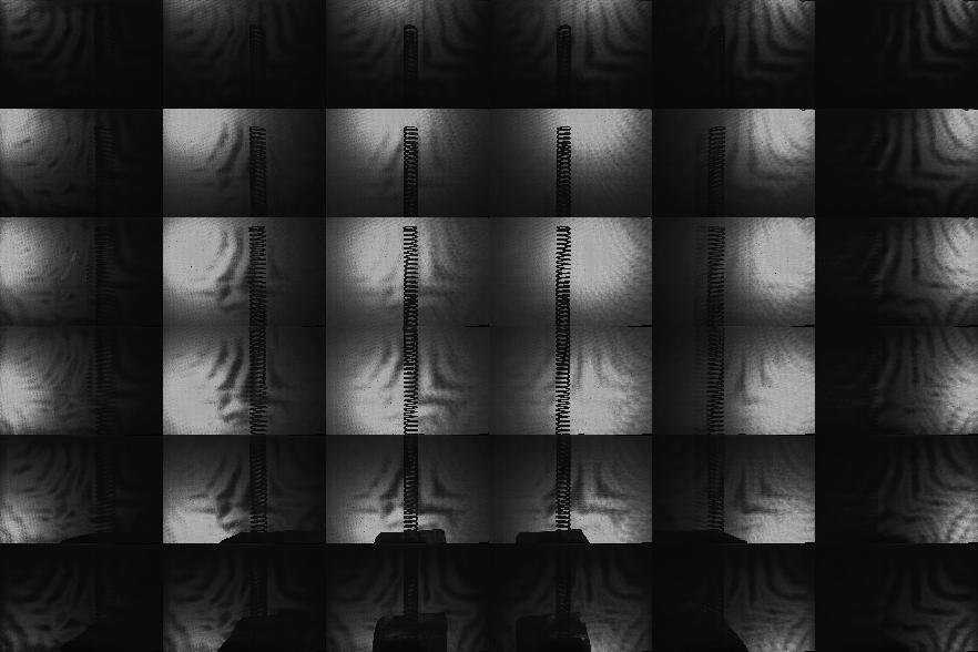
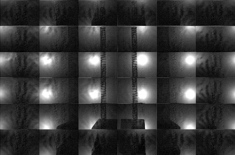
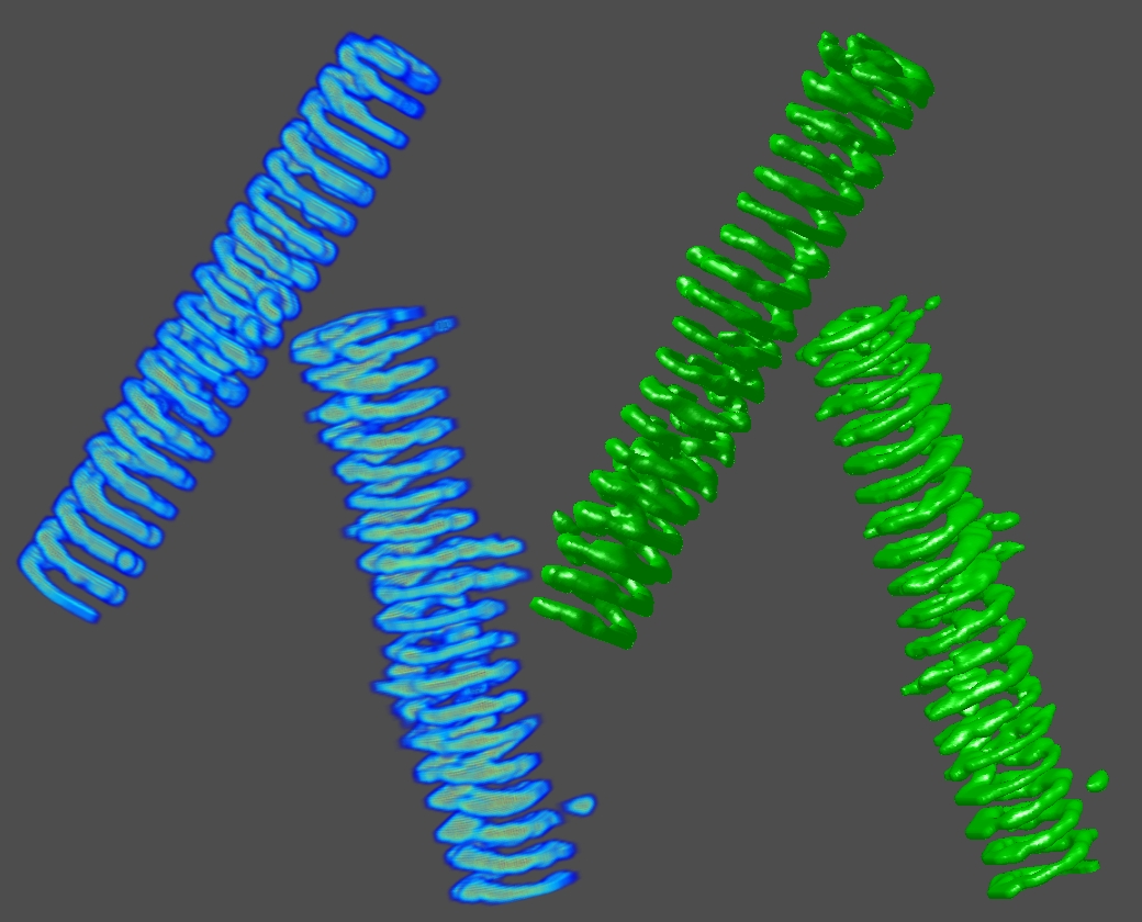
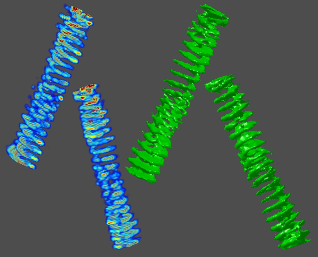
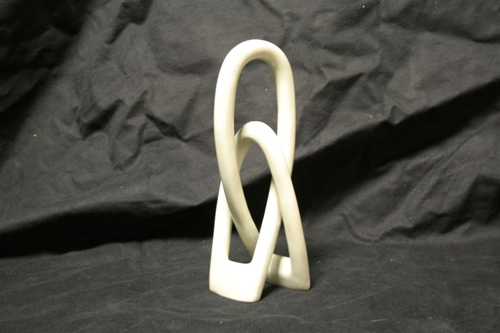
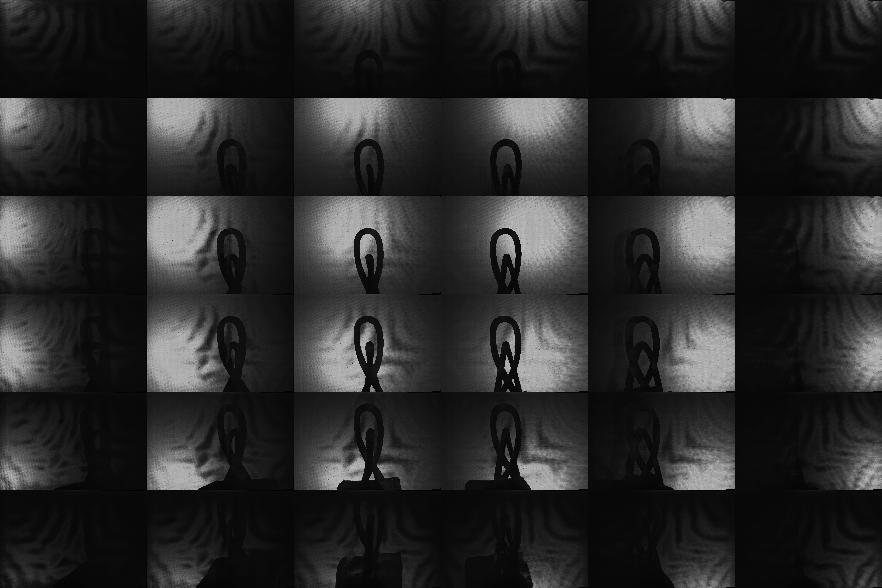
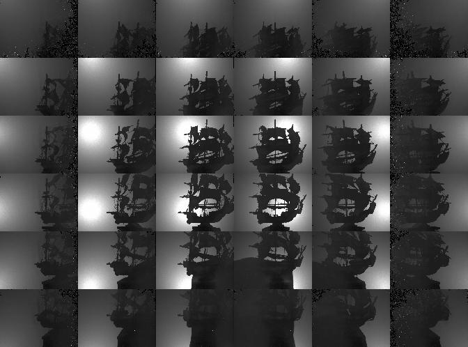
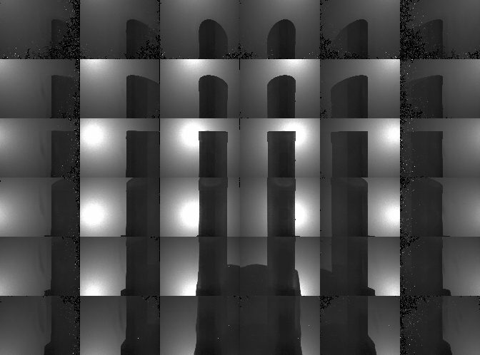
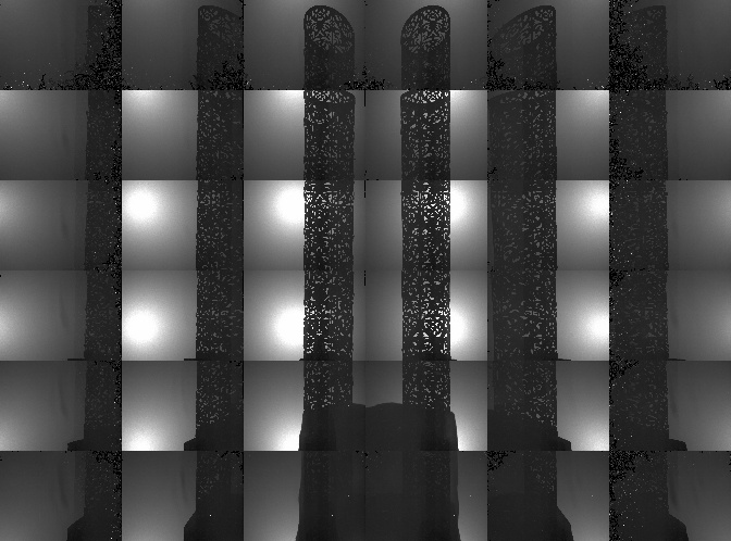
This table summarizes the performance of our prototype implementation for a variety of objects; the first column shows a summary of objects which we have tested with our system. The second through seventh columns compare the performance of the "pinhole array" and "tiled-MURA" masks using our photographic prototype. (Note that the object placement and orientation differs between the "pinhole array" and "tiled-MURA" examples.) We again emphasize that, in our method, each frame is reconstructed independently. These photographic results demonstrate that single-frame reconstruction was achieved. We also note that the benefits of the "tiled-MURA" mask are clear from these examples; in each case, the pinhole array required a 30 sec. exposure, whereas the tiled-MURA mask required only 0.25 sec. (over 100 times shorter). Note that the visual hull reconstructions are displayed as volume renderings and isosurfaces. (The transfer function for the volume renderings was manually-tuned so that high-confidence regions are shaded red, moderate-confidence regions in green, and low-confidence regions in blue.) While qualitatively similar, we note that obtaining individual shadowgrams using "tiled-MURA" masks requires better calibration in order to obtain the proper phase-shifts for demodulation (unlike the "pinhole array" images). Please note that all videos were encoded using the Xvid codec.
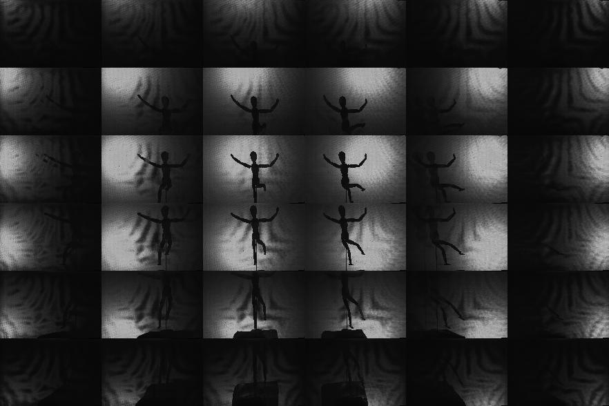
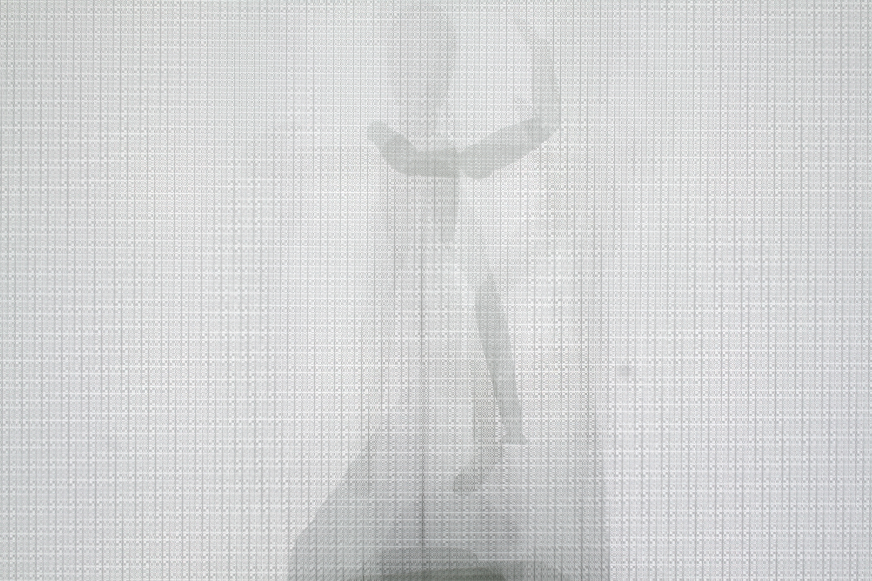
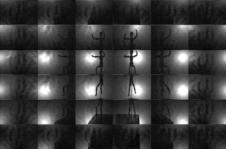
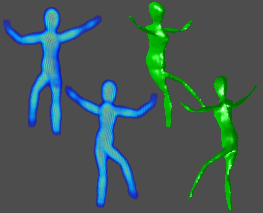
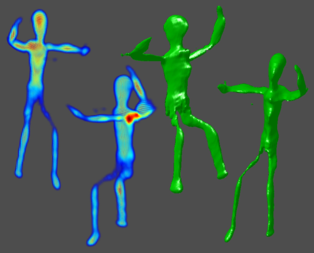
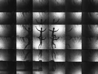
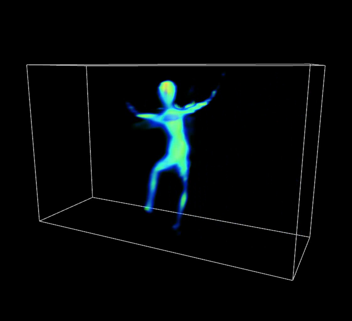
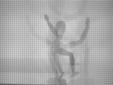
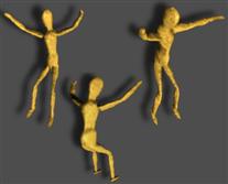
Comments on Video-rate Results:
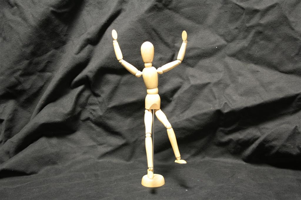
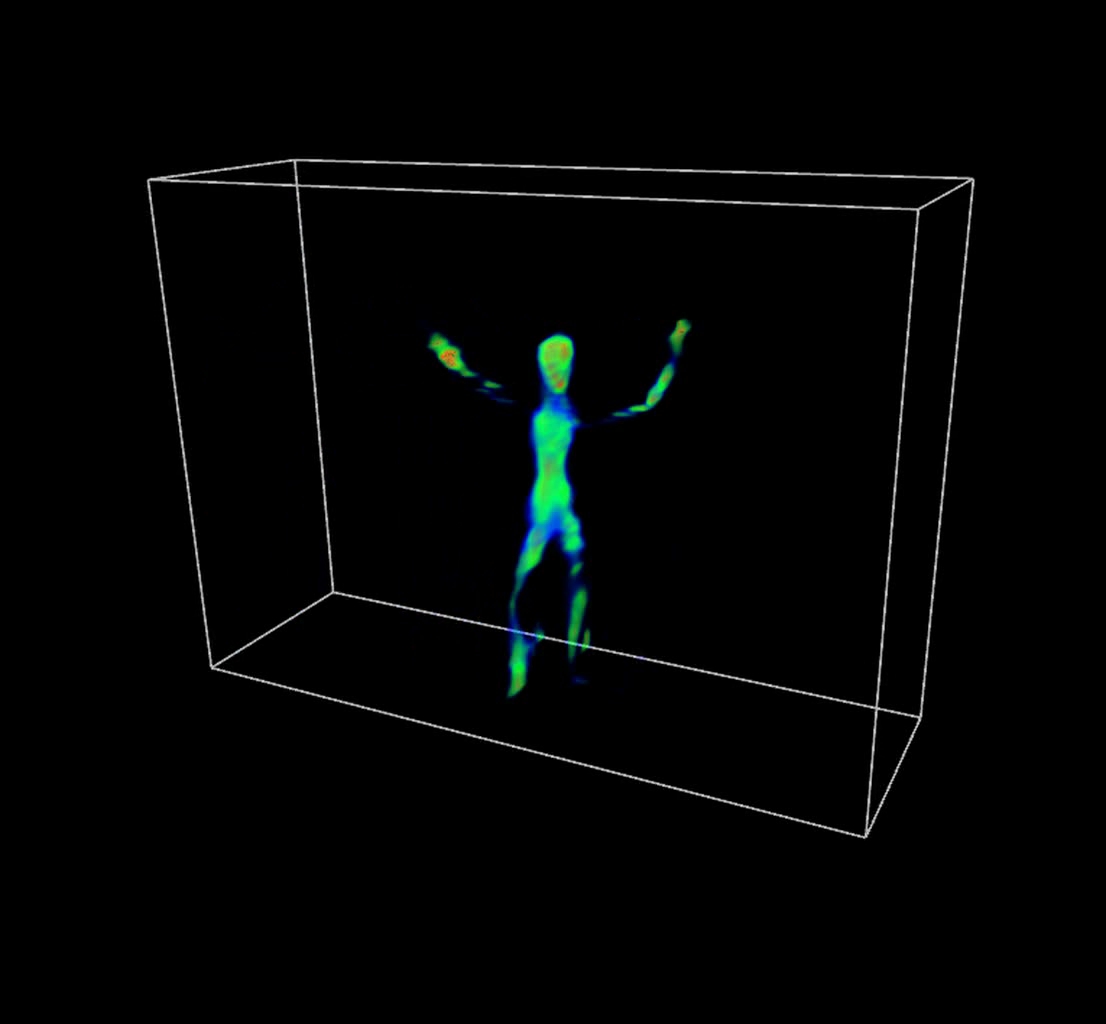
The resolution of current video camera technology limits the degree to which we could demonstrate real-time capture; we have, however, implemented a preliminary video-rate version of our prototype using a Point Grey Grasshopper video camera capable of recording 1600x1200 8-bit RGB images at 15 fps; typical results are demonstrated in columns eight through thirteen. Note that, since these dynamic examples are a proof-of-concept to confirm video-rate performance, only a single example is considered: that of a rigidly-mounted mannequin translated throughout the reconstruction volume over 10 seconds. Note that the volume renderings were also generated using Drishti. (The transfer function was again manually-tuned so that high-confidence regions are shaded red, moderate-confidence regions in green, and low-confidence regions in blue.) Please click on any image to view at higher-resolution or to view the associated video for dynamic examples. Due to the reduced resolution of the video camera, the recovered light field consists of a 6x6 array of approximately 75x50 pixel images for the dynamic examples, whereas the photographic implementation allowed the recovered of a 6x6 array of approximately 150x100 pixel images. Again, the most significant practical limitation of our system is the diffuser (and the video-rate results show similar limitations in this regard). We believe that these limitations can be overcome with careful engineering and utilization of improved optical components. In the future, higher resolution projectors will lead to similar improvements in commercial rear-projection diffusers. Alternatively, as discussed in Section 8, we could increase the size of the system; since the diffuser PSF stays constant, but the size of a camera pixel increases, the effective angular resolution will increase. Finally, we emphasize that our system will scale with improvements in camera sensors. For example, with a 100 megapixel camera, our design will capture a 10x10 array of 1 megapixel images; in comparison, consider the challenge and costs of building a comparable system with 100 individual cameras.
General Comments on Current Limitations:
We again emphasize that, while the current results show some reconstruction errors, we believe careful engineering, the inclusion of future diffuser technology, and high-resolution consumer cameras will greatly improve the quality of the results and the practicality of the proposed architecture. When viewing these results, please weigh current limitations against the considerable promising new directions enabled by our theory and system, including: (1) allowing single-camera techniques to compete, for the first time, with complex multi-camera systems in the arena of motion capture, and (2) developing high-throughput attenuation masks for use in heterodyne light field cameras and large-format photography.
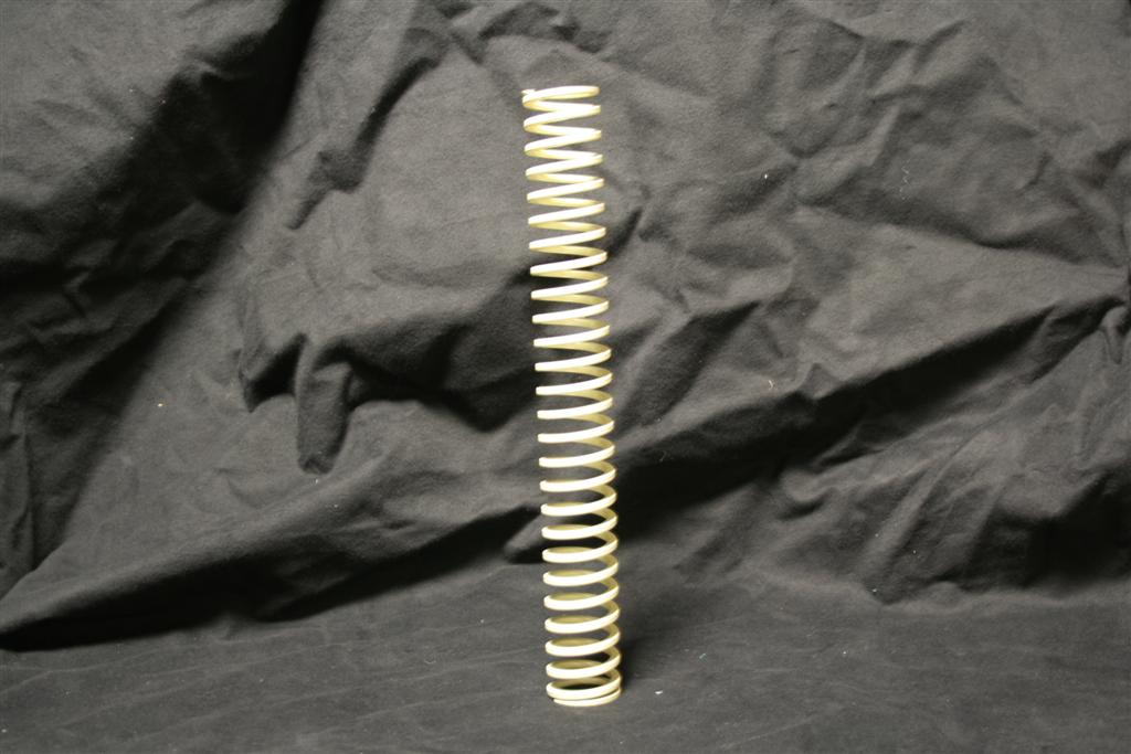
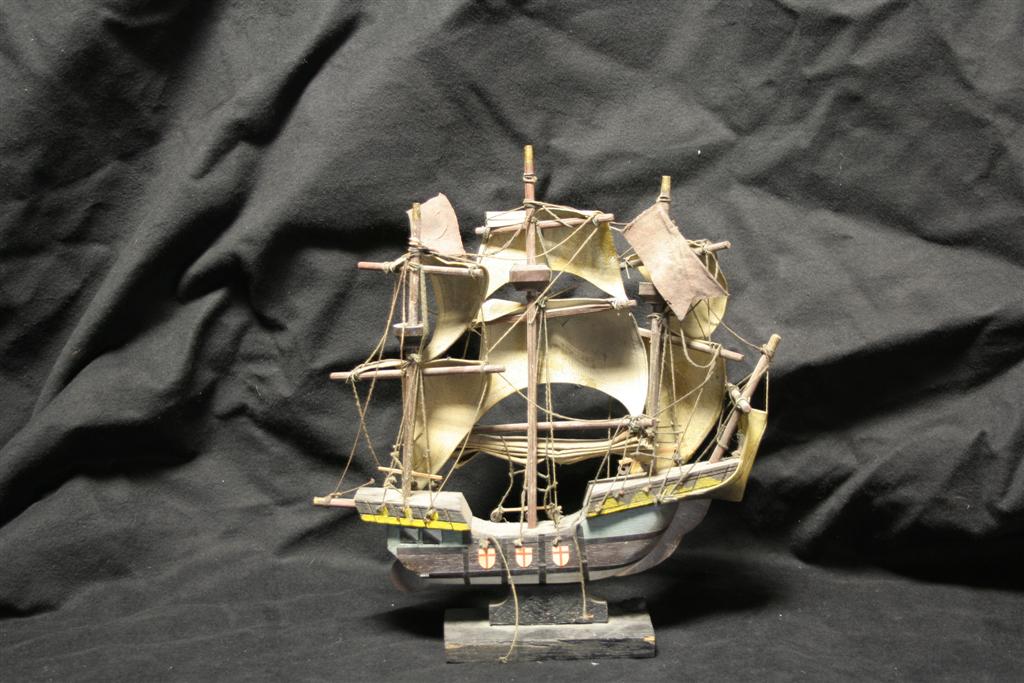
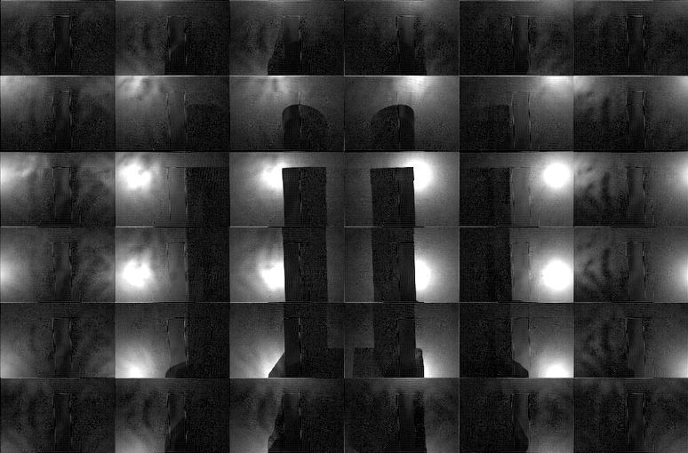
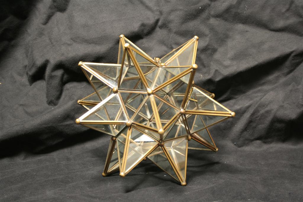
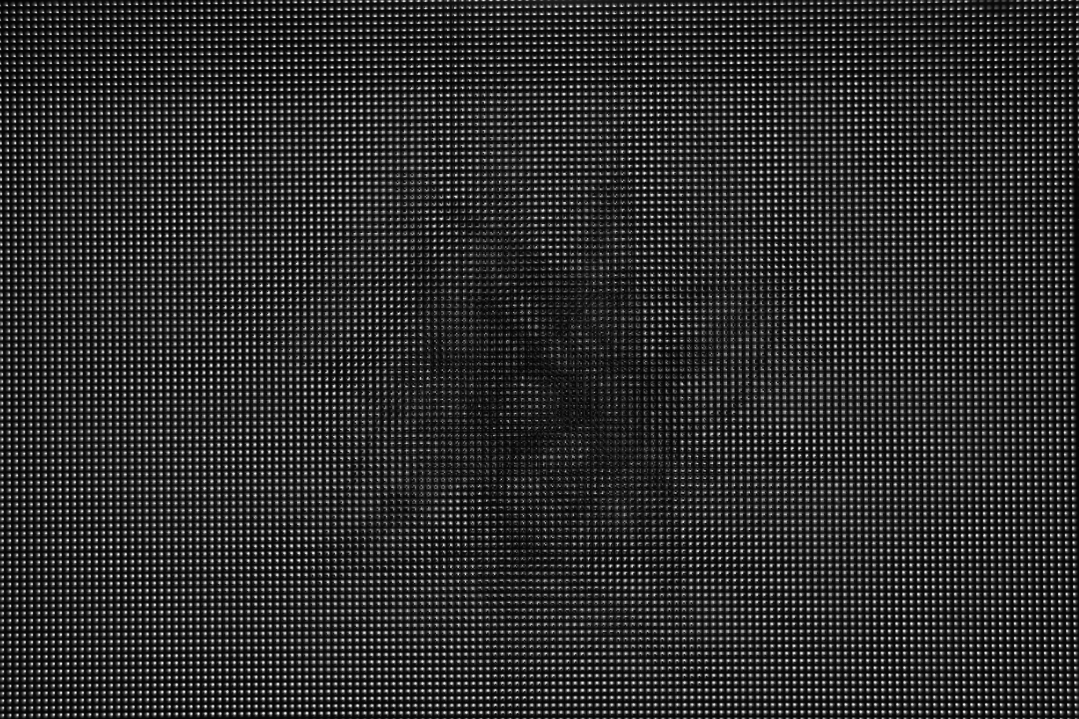
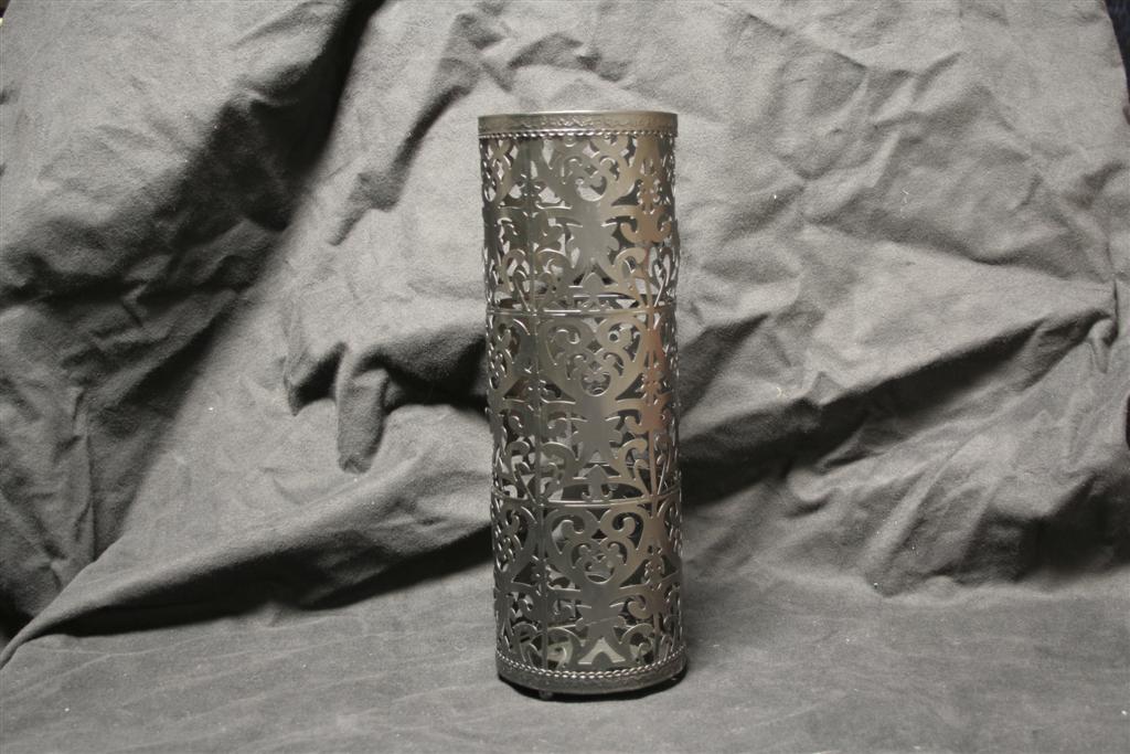
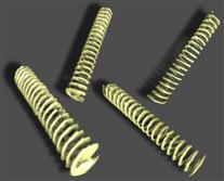
| Test
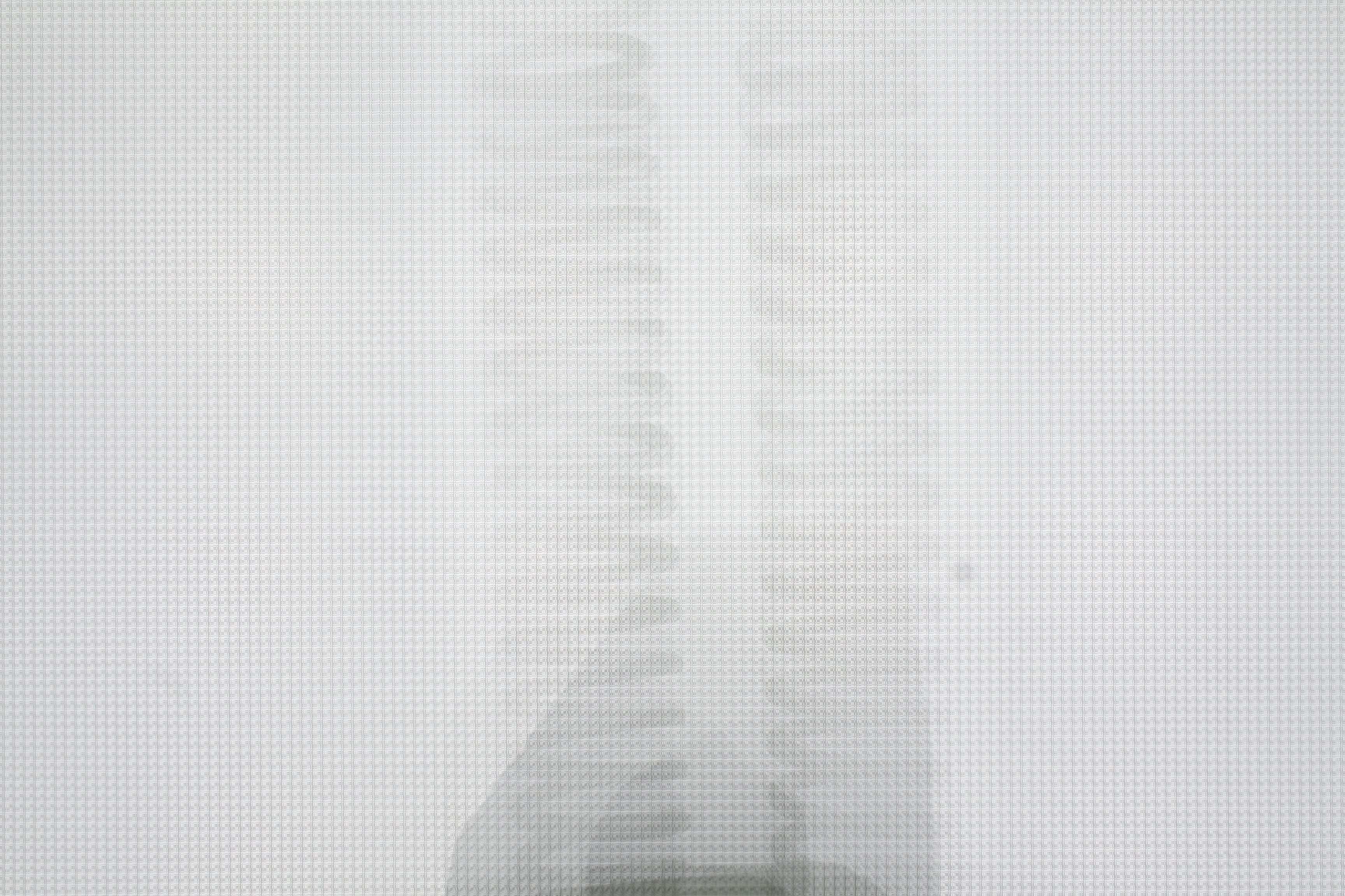
Object (Photographed Separately) |
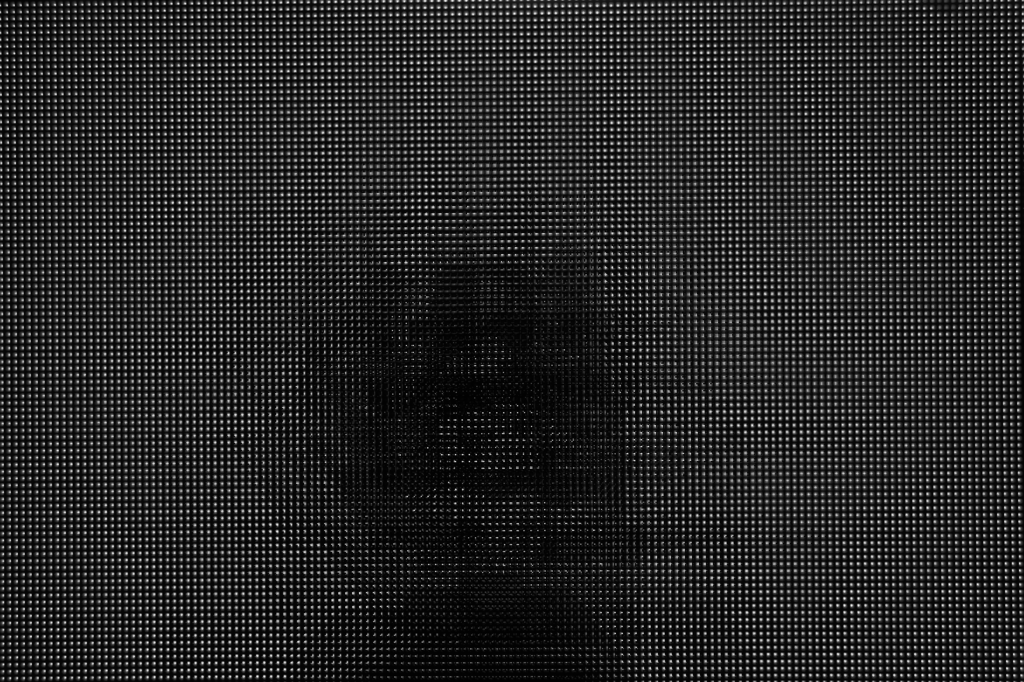
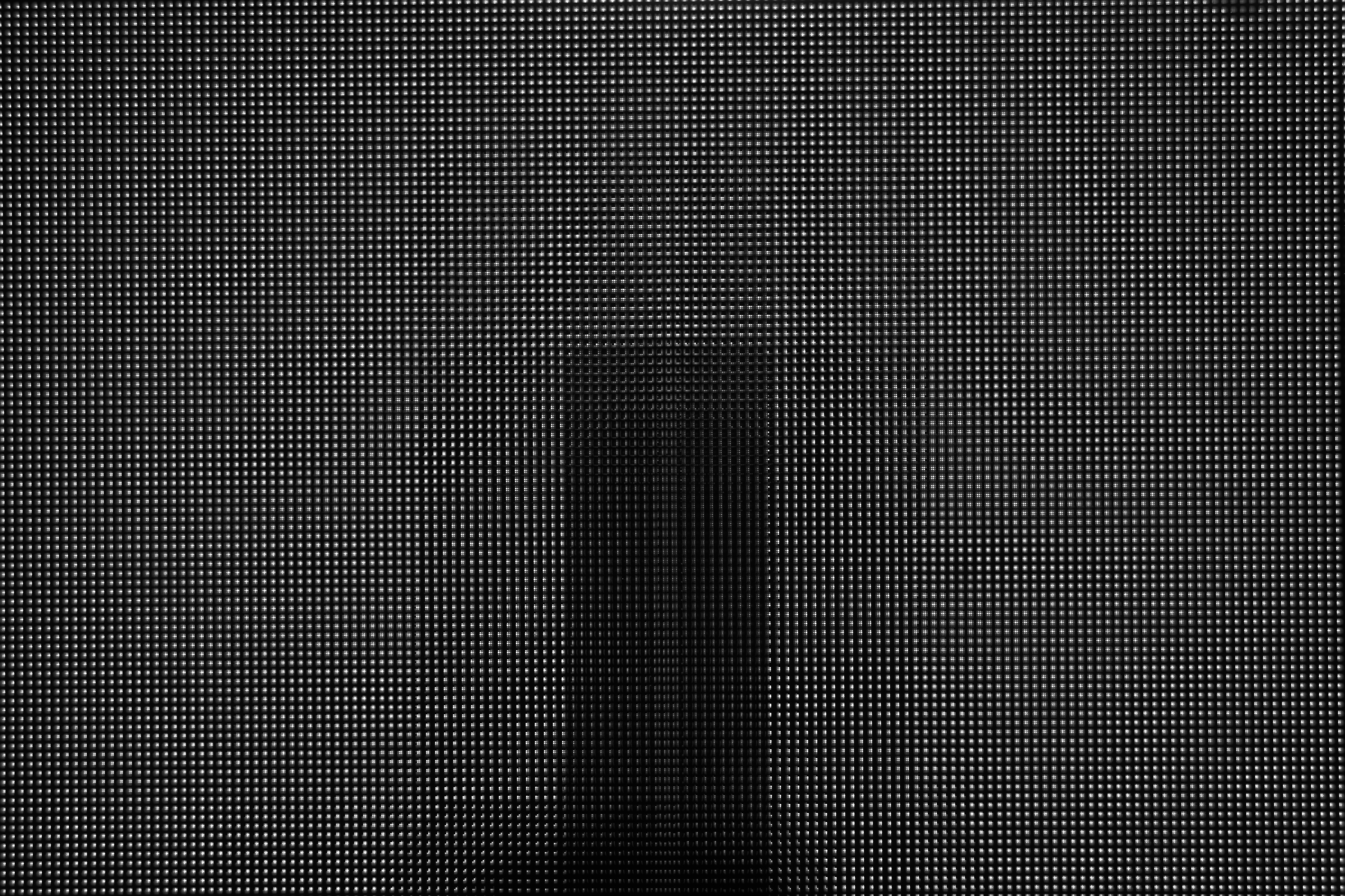
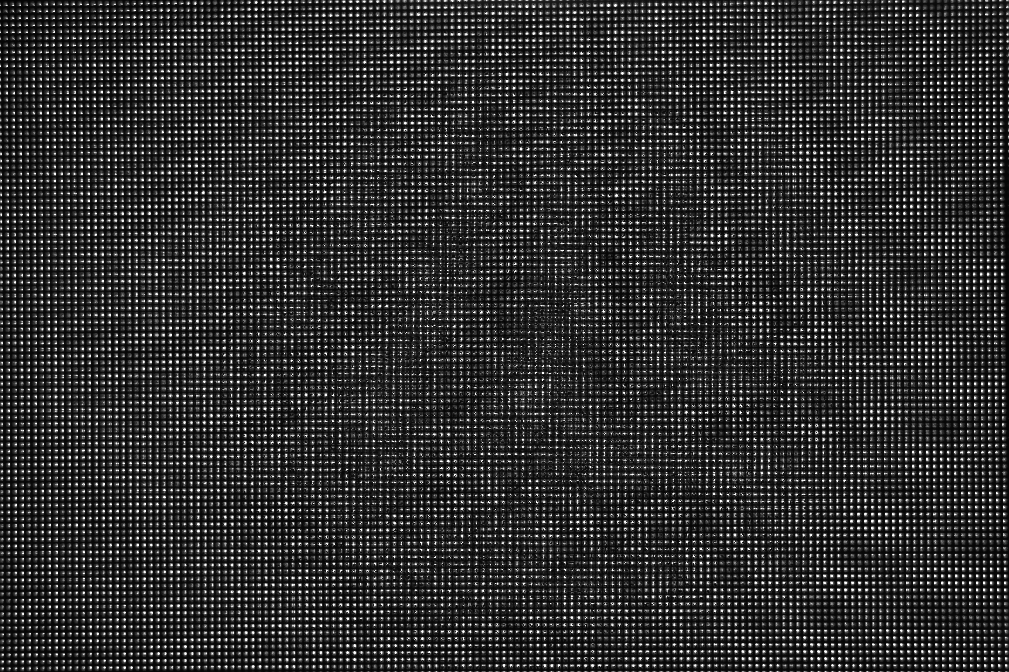
Sensor
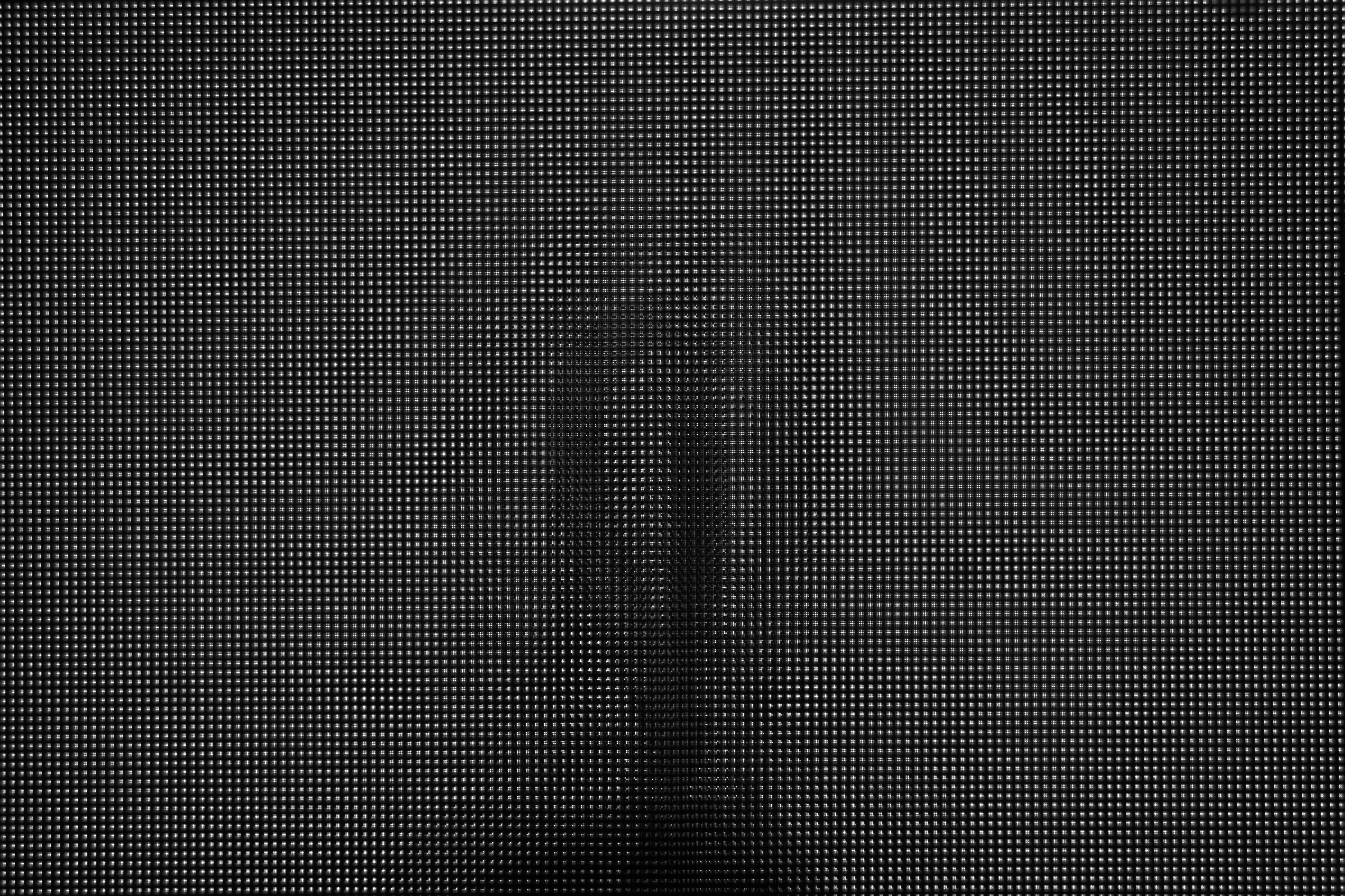
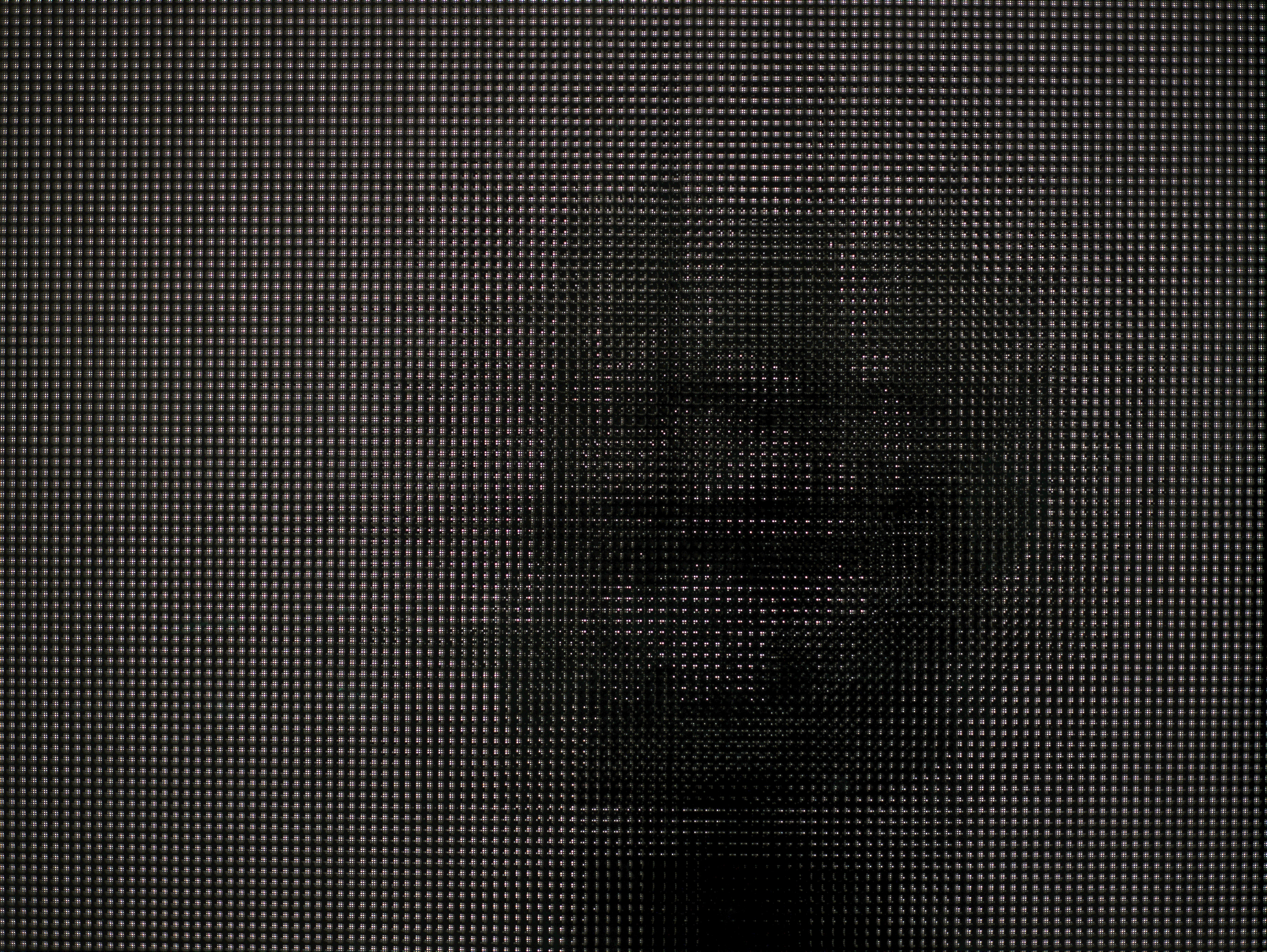
Image ("Pinhole Array", 30sec Exposure) |
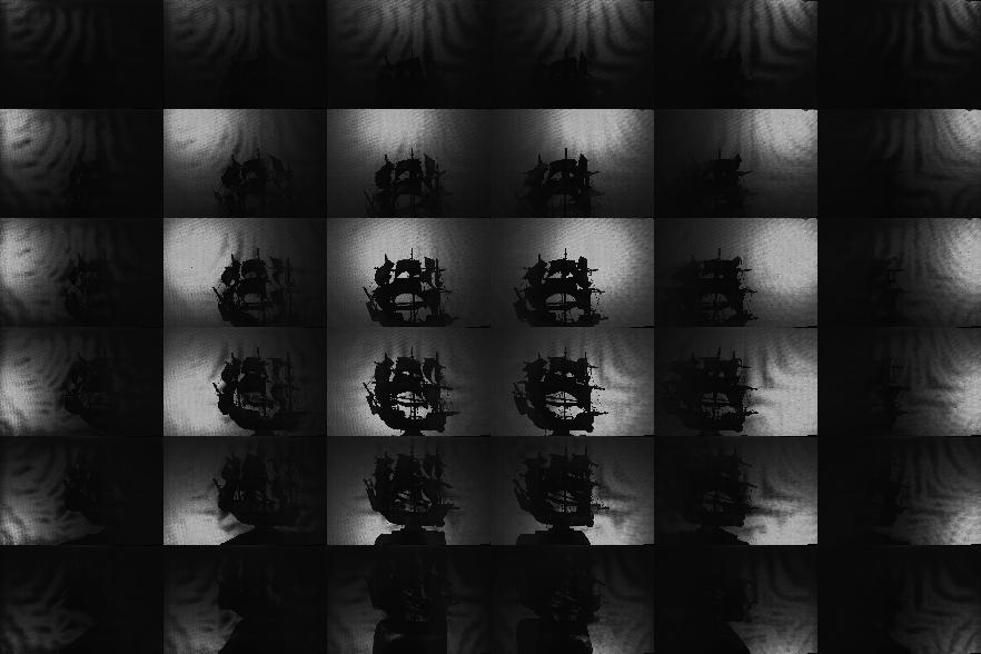
Recovered
6x6 Shadowgrams ("Pinhole Array") |
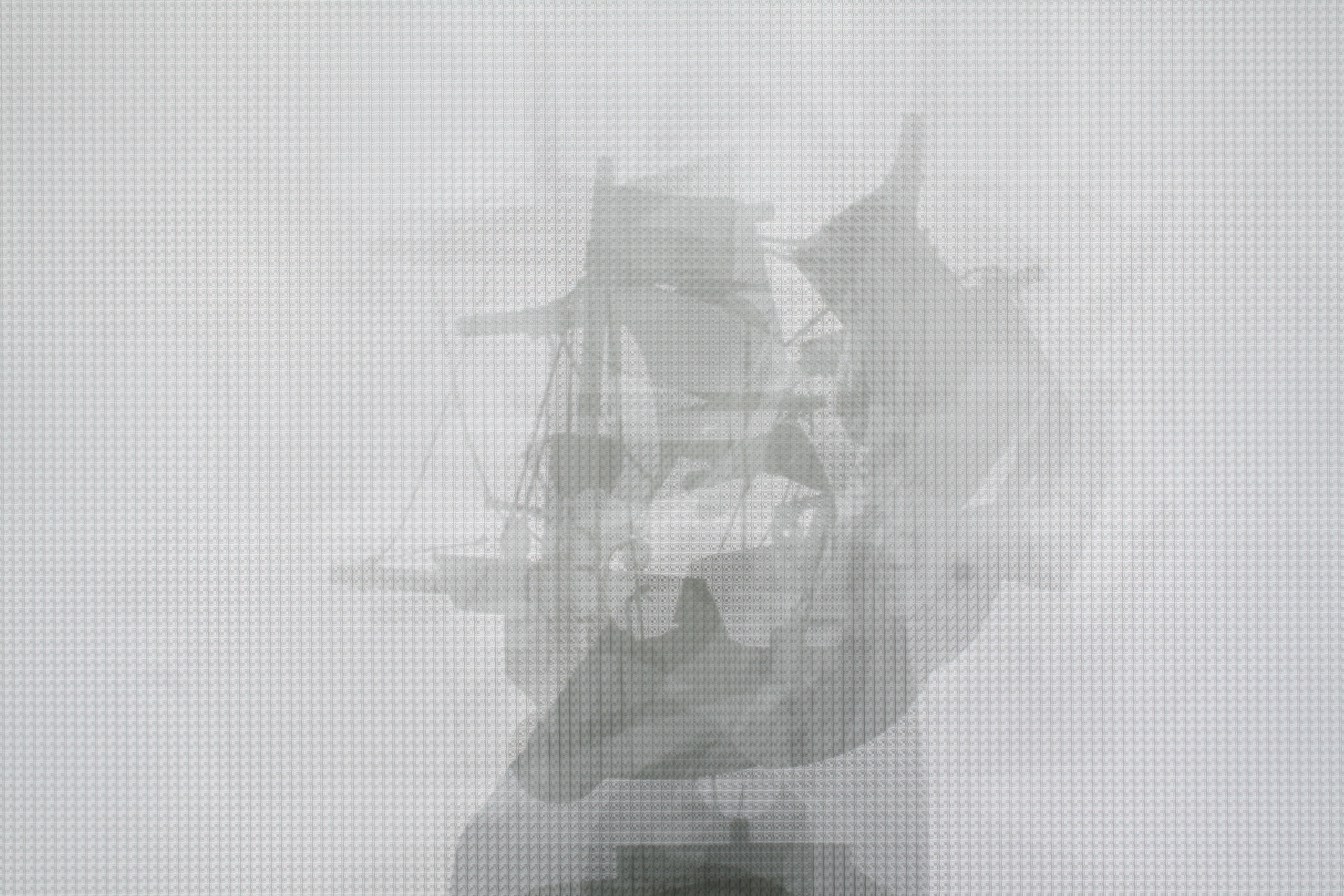
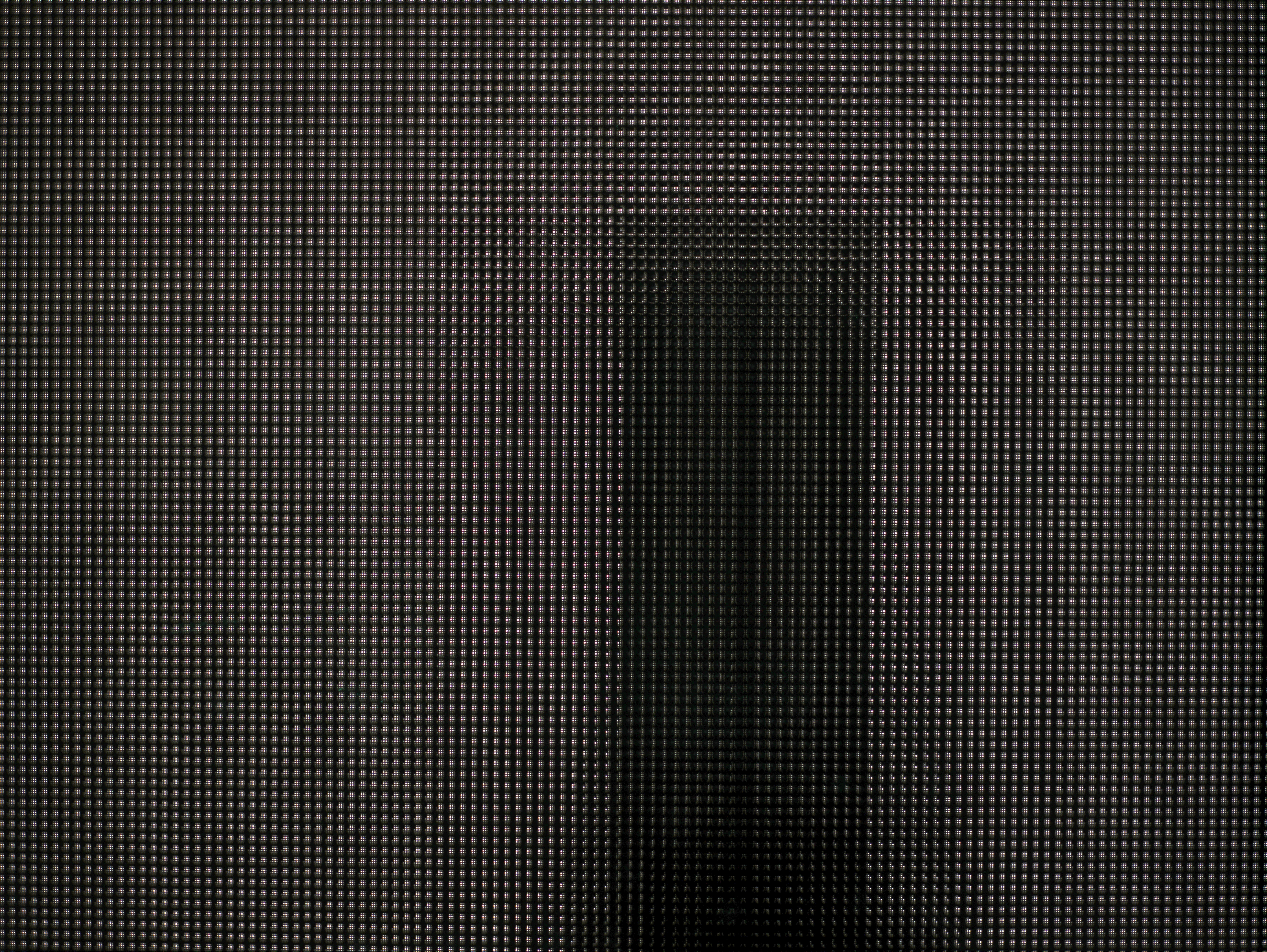
Sensor
Image ("Tiled-MURA", 0.25sec Exposure) |
Recovered
6x6 Shadowgrams ("Tiled-MURA") |
Recovered Visual Hull ("Pinhole Array") |
Recovered Visual Hull ("Tiled-MURA") |
Sensor
Video for Dynamic Scene ("Pinhole Array") |
Recovered
6x6 Shadowgrams ("Pinhole Array") |
Visual
Hull Reconstruction ("Pinhole Array") |
Sensor
Video for Dynamic Scene ("Tiled-MURA") |
Recovered
6x6 Shadowgrams ("Tiled-MURA") |
Recovered
Visual Hull ("Tiled-MURA") |
 |
 |
 |
 |
 |
 |
 |
 |
 |
 |
 |
 |
 |
 |
 |
 |
 |
 |
 |
 |
||||||
 |
 |
 |
 |
 |
 |
 |
||||||
Additional examples showing improvement in overall light throughput using "Tiled-MURA": |
||||||||||||
| Test
Object (Photographed Separately) |
Sensor
Image ("Pinhole Array", 30sec Exposure) |
Recovered
6x6 Shadowgrams ("Pinhole Array") |
Sensor
Image ("Tiled-MURA", 0.25sec Exposure) |
Recovered
6x6 Shadowgrams ("Tiled-MURA") |
||||||||
 |
 |
 |
 |
 |
||||||||
 |
 |
 |
 |
 |
||||||||
 |
 |
 |
 |
 |
||||||||
 |
 |
 |
 |
 |
||||||||
 |
 |
 |
 |
 |
||||||||
 |
 |
 |
 |
 |
||||||||
Light Source Calibration Procedure
In order to recover the visual hull from the individual shadowgrams, we require precise estimates of the 3D location of each point source. Previously, Yamazaki et al. [2007] and Savarese et al. [2001] studied the problem of estimating the position of point light sources. For our system, we adopted a method similar to Yamazaki et al. [2007]. As discussed in that work, the position of a point light can be recovered by observing the shadows due to spheres placed within the scene. In fact, they show that one can solve for the position of a light in 3D given two or more images of a single sphere with an unknown radius. In this work, we used a single sphere, with a 12.7cm diameter, and recorded a set of shadowgrams as the sphere was translated through the reconstruction volume. Typical shadowgrams are shown below. Afterwards, we used a least-squares ellipse-fitting routine to estimate the shadow boundary. To minimize the effects of outliers and shadowgram artifacts, we further applied RANSAC within the ellipse-fitting procedure. Typical fitting results are shown below (with the ellipse boundary shown in green and the major/minor axes shown in blue/red). The complete set of ellipses are also shown below, where we observe that, in 2D, their major axes intersect the closest point in the diffuser to each light source. Again, one must apply RANSAC to minimize the effects of poorly-fit shadow boundaries. Finally, the full ellipse parameters are used to recover the depth of each light source. The recovered light source positions are shown below. In this example, we have found the best location of the light source array, given the constraint that the lights are uniformly-distributed and that the predicated shadow boundaries are as close as possible to the detected ellipses.
 |
 |
 |
 |
| Recovered Shadowgrams ("Pinhole Array", 1.6sec Exposure) |
Ellipses Fit
using Least-Squares with RANSAC ("Pinhole Array", 1.6sec Exposure) |
 |
 |
| Summary of Ellipses
Fit to 16 Calibration Images ("Pinhole Array", 1.6sec Exposure) |
Recovered Light
Source Positions ("Pinhole Array", 1.6sec Exposure) |
Compensating for Refraction within the Multiple Glass Panes
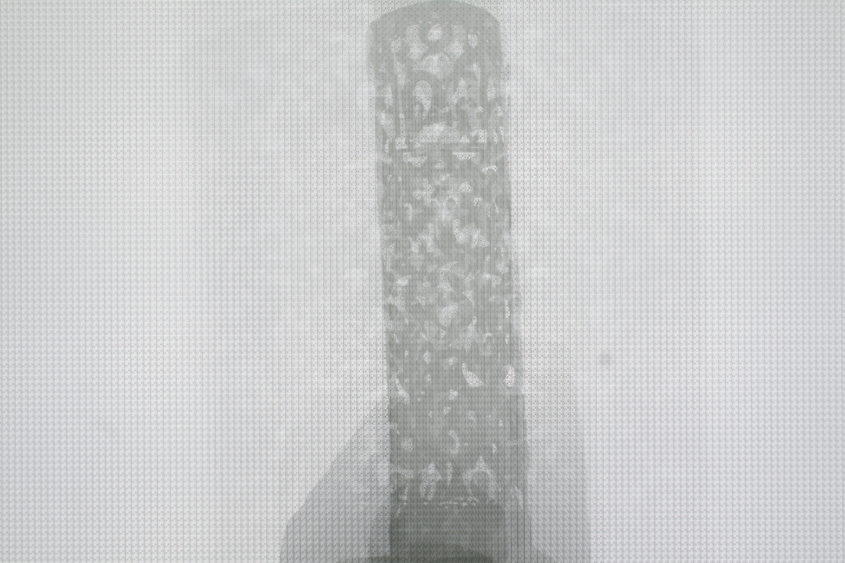
Observations of Per-Pinhole Barrel Distortion due to Glass Refraction:
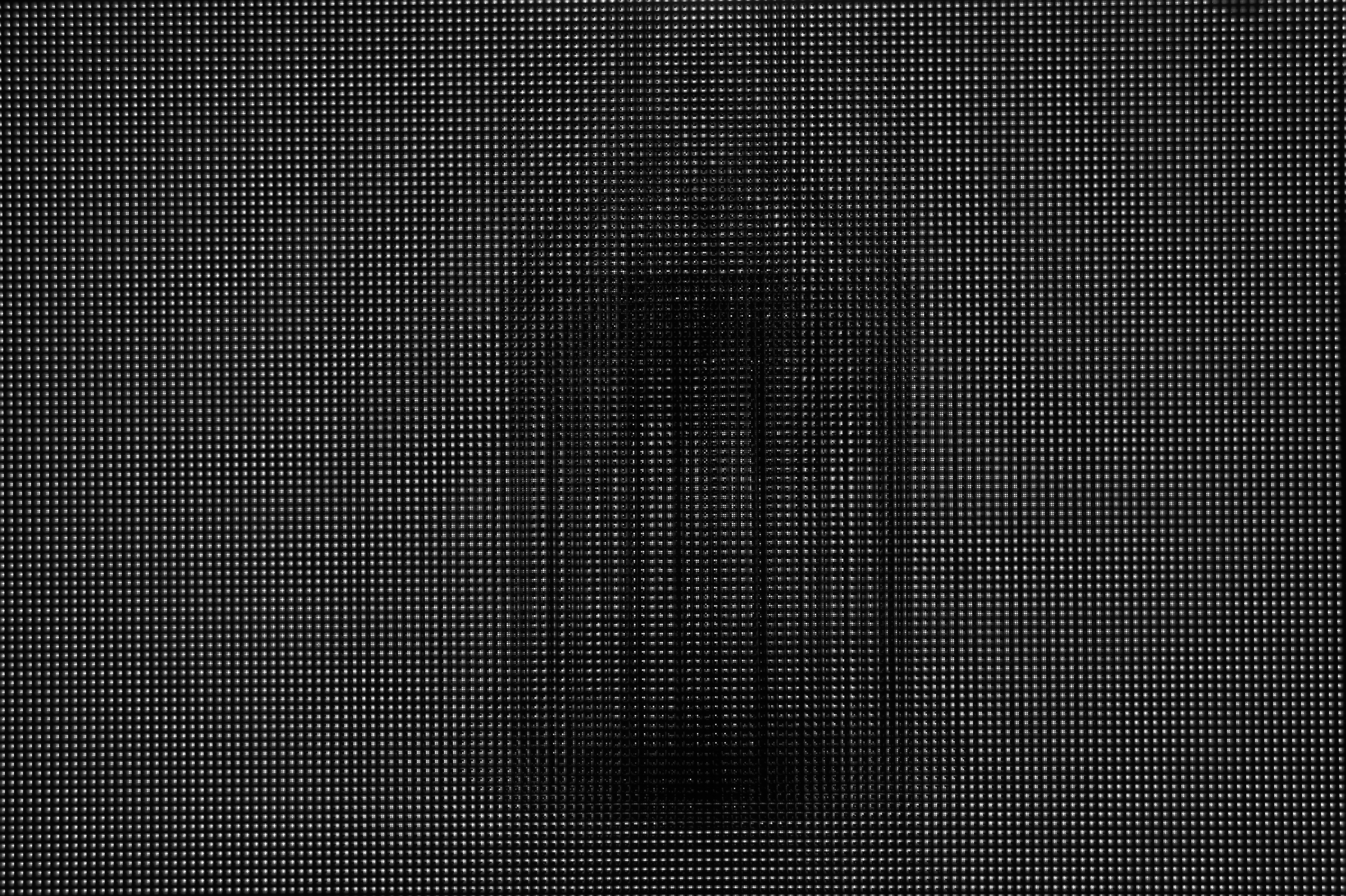
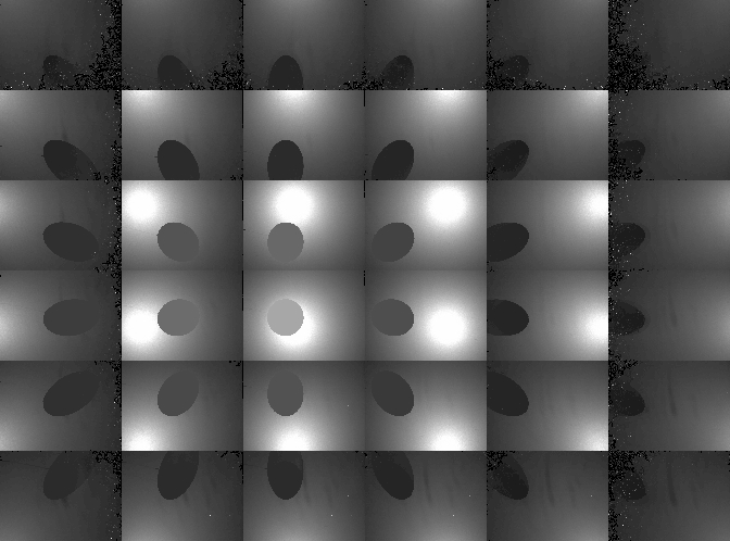
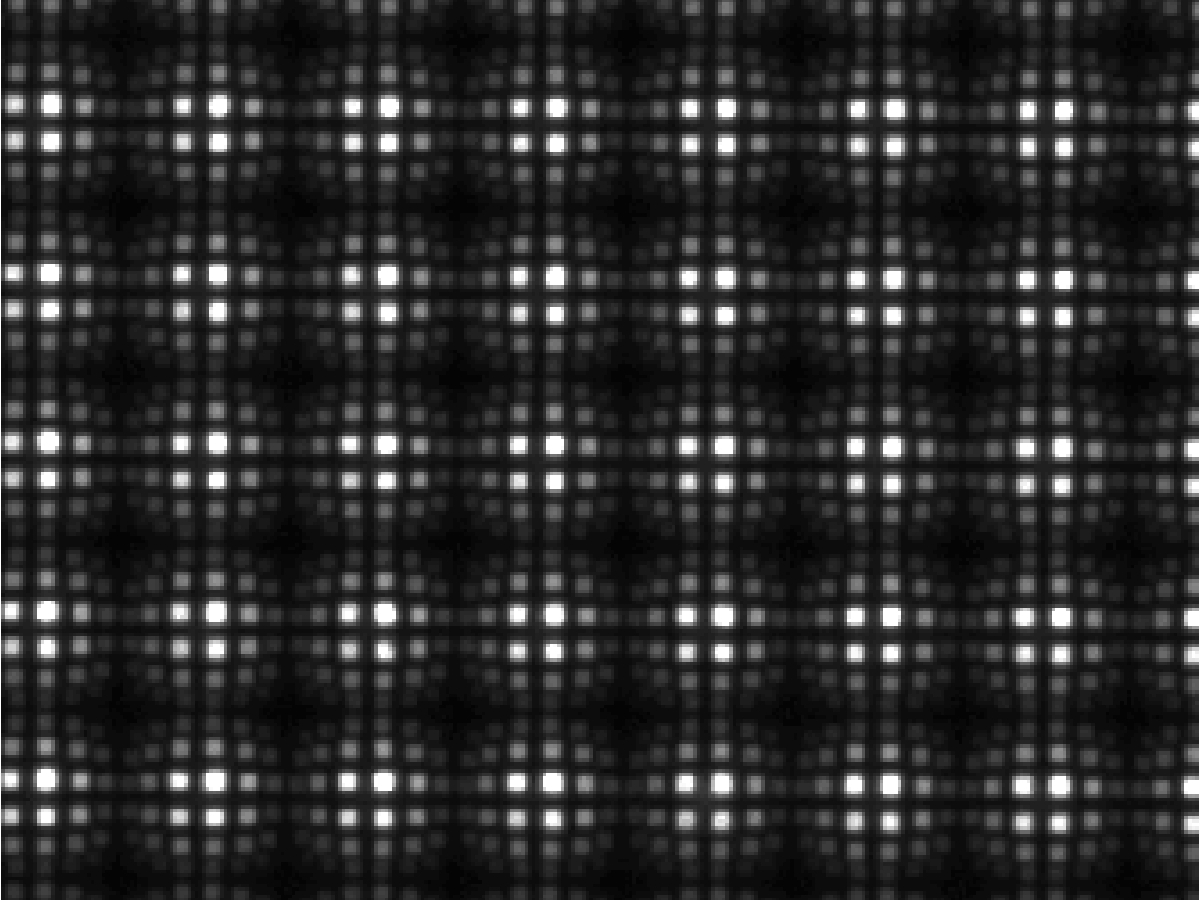
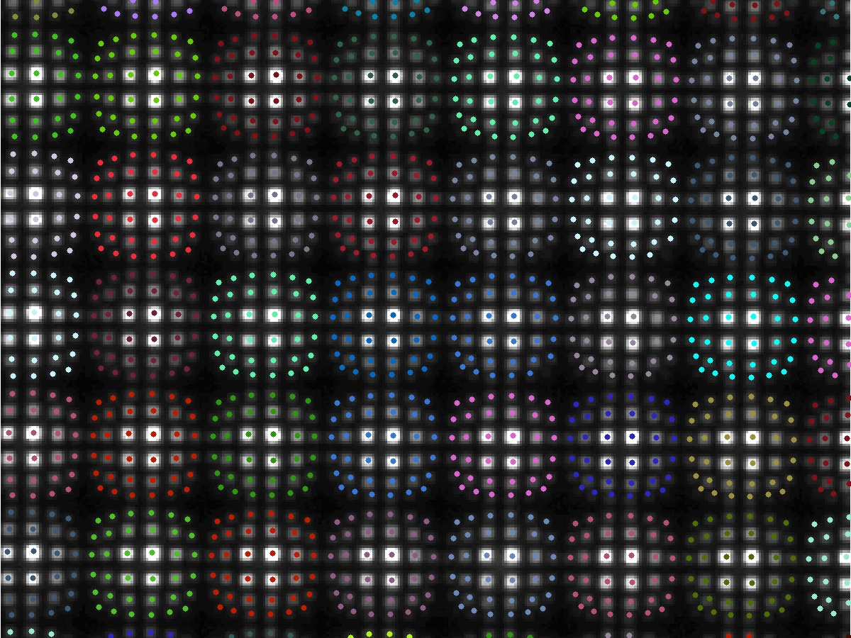
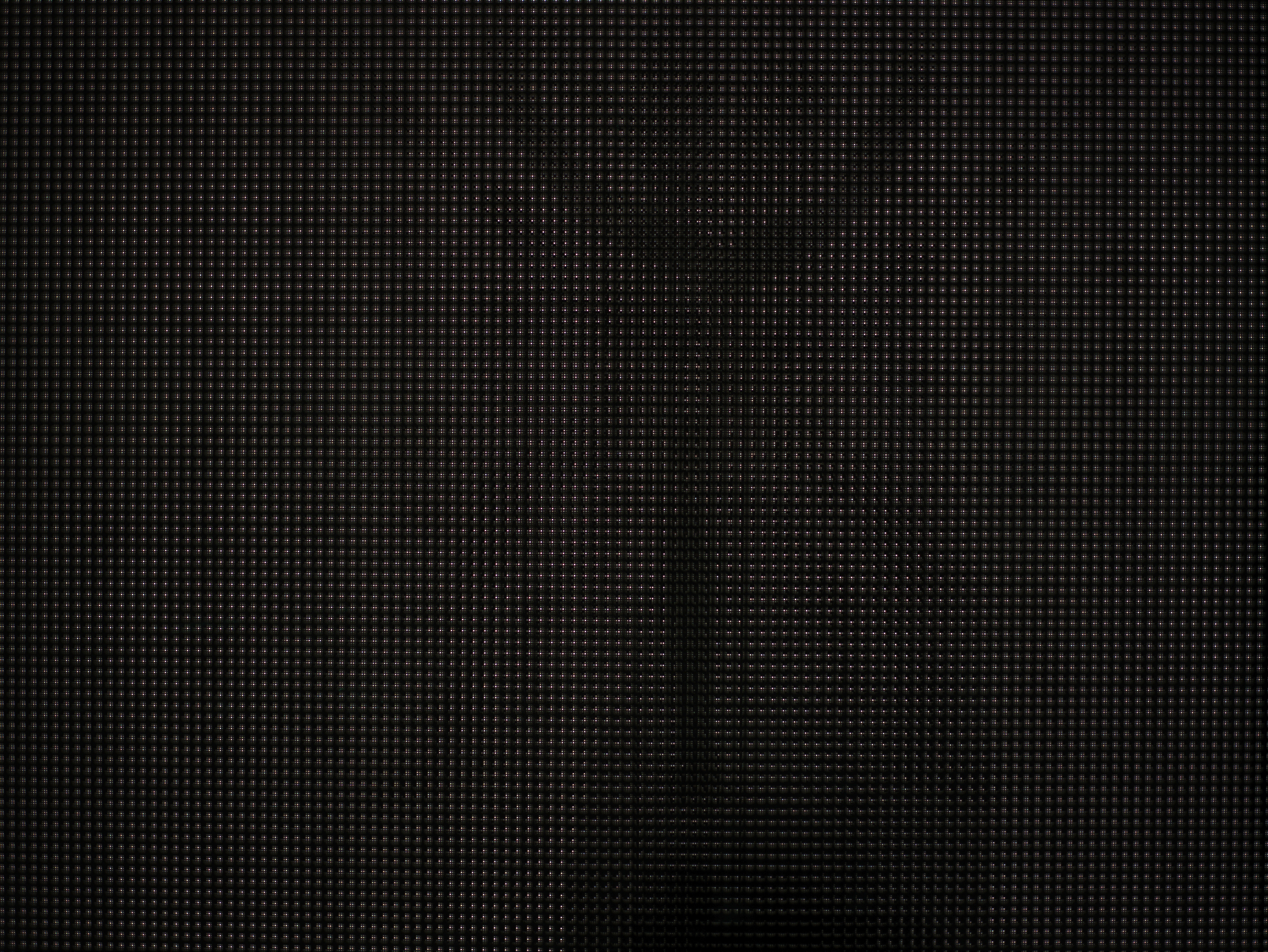
In the prior results, we ignored the effect of refraction due to the multiple thin glass panes. In general, we find that refraction is a significant issue and, to obtain the highest-quality shadowgrams, one must compensate for its effects. The effects of refraction are readily observed by illuminating the scene with the 6x6 LED array and recording a shield field photograph using a pinhole array mask. As shown in the images above and in the inset region below, a per-pinhole barrel distortion is clearly present. If refraction was not an issue, then the image of each point light source would be located in a uniformly-spaced grid (rather than a barrel-distorted pattern). In our prototype, neither the attenuating masks nor the diffuser are rigid. As a result, we must use a minimum of three sheets of approximately 2.7 mm glass to separate the mask from the diffuser and hold both in fixed positions.
Theoretical Explanation for Barrel Distortion:
Generally, the thickness of the glass after the diffuser does not significantly impact the barrel distortion, however it does slightly increase the effective PSF of the imaging system. Surprisingly, the thickness of the first sheet of glass (between the mask and the light sources) is important and should be as thick as possible. This is somewhat counterintuitive, however it is easily explained using geometric optics. First, notice that the second sheet of glass (between the mask and diffuser) must have the precise thickness required for heterodyne detection (i.e., the mask-diffuser separation is given by the desired spatial/angular resolution and the geometric placement of the lights relative to the diffuser). Since the refractive index of crown glass is around 1.5, the effect of the center glass sheet will be to bend each incident ray towards the surface normal of the pane – directly causing the observed barrel distortion. As a thought experiment, now consider varying the thickness of the first sheet of glass from zero (i.e., no glass) to the distance to the light array (i.e., infinite). If the glass thickness is zero, then we have the case of a single glass sheet between the mask and diffuser, and significant barrel distortion occurs. If we enclose the lights within the glass, then no refraction occurs before the pinhole or before the diffuser and it is as if the system is in air. As a result, increasing the thickness of the first glass sheet slightly reduces barrel distortion. In practice, however, barrel distortion cannot be eliminated in our current design. In the future, we propose using rigid masks and diffusers to avoid refraction. Most importantly, we observe that if a revised design only eliminated the central glass pane, then barrel distortion would be completely eliminated for the pinhole array – even if the other two panes of glass remained in the system.
Compensating for Barrel Distortion in Pinhole Arrays:
While the prior results demonstrate successful shadowgram recovery, we notice that, by ignoring refraction, the demodulated pinhole array and tiled-MURA results exhibit various moiré-type patterns. This is a result of assuming that the images of the point sources are located on a uniform grid. Because the barrel distortion is minor, this does not prevent either pinhole or heterodyne masks from functioning, however better results can be achieved by compensating for refraction. Currently, this procedure can only be applied to pinhole array images, but we expect future work to examine similar solutions for heterodyne demodulation. To compensate for refraction, we simply photograph an empty scene using a pinhole array mask and a single light source at a time. In our prototype, we collect 36 images – one for each LED. Afterwards, we detect the subpixel peaks (using intensity centroids) for each pinhole image. Finally, after grouping and ordering these peaks, we obtain the per-pinhole barrel distortion (as shown below on the right). Afterwards, we use the subpixel peaks to interpolate any given shield field photograph. As shown in the following section, this procedure produces enhanced shadowgrams with minimal crosstalk and with better performance for large angles of incidence to the diffuser.
 |
 |
| Inset Region of
Sensor
Image ("Pinhole Array", 1.6sec Exposure) |
Estimated
Intensity-Centroids for Each Image Peak ("Pinhole Array", 1.6sec Exposure) |
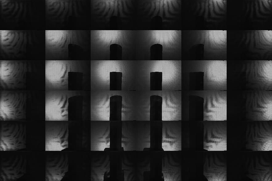
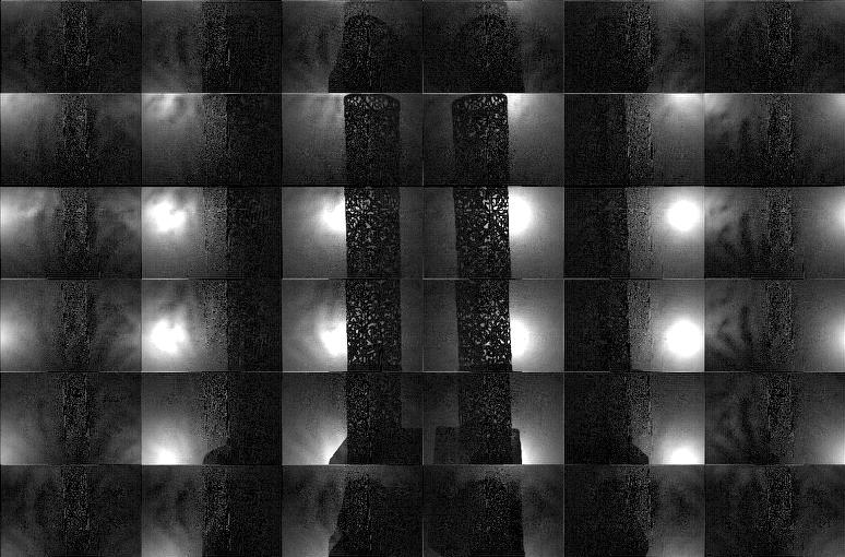
Results: Refraction-Compensated Shadowgram Recovery and Visual Hull Reconstruction
We repeated the previous photographic shield field experiments using the refraction compensation procedure. In addition, because the per-pinhole barrel distortion may cause image peaks to move closer together, we also used a higher-resolution camera to prevent undersamping. In these examples we used a 22 megapixel Mamiya 645ZD camera with an 80mm f/2.8 AF lens. In addition, we photographed the diffuser using the maximum setting of f/2.8 – significantly reducing the necessary exposure time for the pinhole array when compared to the Canon EOS Digital Rebel XT. Typical results are shown below. Note that the peripheral shadowgrams (corresponding to large angles of incidence to the diffuser) are more robustly recovered than before, where the remaining "salt-and-pepper" noise results from peak-localization errors in low-SNR regions of the recovered shadowgrams. Similarly, visual hull reconstructions using the refraction-compensated shadowgrams recovered finer object details.
| Test
Object (Photographed Separately) |
High-Resolution
Sensor
Image ("Pinhole Array", 1.6sec) |
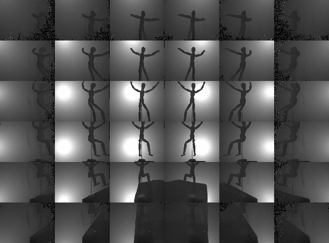
Recovered
6x6 Shadowgrams
Refraction Compensated ("Pinhole Array") |
Recovered Visual Hull Refraction Compensated ("Pinhole Array") |
|
 |
 |
 |
|
 |
 |
 |
|
 |
 |
|
|
 |
 |
|
|
 |
 |
|
|
 |
 |
|
|
 |
 |
|
|
 |
 |
Conclusion
Occluders are becoming valuable for a range of Computational Photography research problems. We have described a unified representation of occluders in light transport and photography using shield fields: the 4D attenuation function which acts on any light field incident on an occluder. We have provided a complete analysis of their application to the inverse problem of occluder reconstruction, leading to the development of new tiled-broadband codes. Our tiled-coding leads to a simple scanning system. We believe we have presented the first single-camera, single-shot approach to capture visual hulls without moving or programmable illumination. Shield fields can be used for several interesting applications in the future, including efficient shadow computations, volumetric/holographic masks, and for modeling general ray-attenuation effects as 4D light field transformations. By creating the signal processing framework and practical light-efficient solutions, we hope to inspire research in novel capture devices based on large area emitters and sensors.